

TROUBLESHOOTING AND ELECTRICAL SYSTEM
Test Procedures
2001 Pioneer 900 Gasoline Vehicle Maintenance and Service Manual Page 11-37
11
TEST PROCEDURE 19 – REVERSE BUZZER LIMIT SWITCH
Read DANGER and WARNING on page 11-1.
NOTE: Keep the battery connected while performing this test procedure.
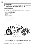
The reverse buzzer limit switch is located on the Forward/Reverse shifter; red/white and orange wires are
connected to it.
1. Place the Forward/Reverse handle in the NEUTRAL position, and chock the wheels.
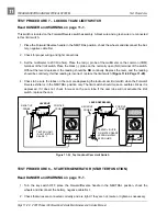
2. Move the Forward/Reverse handle to REVERSE and listen for an audible click from the limit switch. If
there is no click, check the switch for proper alignment and switch arm movement.
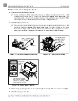
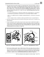
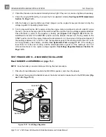
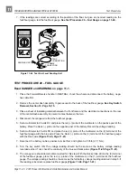
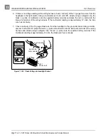
3. If the switch is being activated but the buzzer does not function, place the red (+) probe of the multime-
ter on one terminal and the black (–) probe on the other terminal of the limit switch. Without the lever
depressed, the reading should be NO continuity. Depress the lever and the reading should be continu-
ity. If either reading is incorrect, replace limit switch (Figure 11-7, Page 11-10).
TEST PROCEDURE 20 – REVERSE BUZZER
Read DANGER and WARNING on page 11-1.
The reverse buzzer is mounted to the center dash assembly under the front body.
1. Place the Forward/Reverse handle in the NEUTRAL position, chock the wheels and disconnect the bat-
tery, negative cable first.
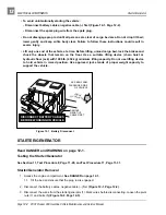
2. To test the reverse buzzer, remove center dash panel. See Key Switch Removal, Section 12,
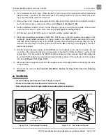
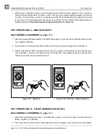
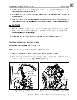
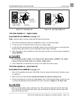
3. Check for proper wiring and tight connections. Using a multimeter, individually check for continuity
through each wire that connects to the reverse buzzer (Figure 11-7, Page 11-10). If the buzzer will not
function when properly wired, replace the buzzer.
TEST PROCEDURE 21 – OIL LEVEL SENSOR
Read DANGER and WARNING on page 11-1.
NOTE: Keep the battery connected while performing this test procedure.
1. Place the Forward/Reverse handle in the NEUTRAL position, turn the key switch to the OFF position,
disconnect the spark plug wire, and chock the wheels.
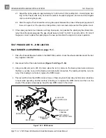
2. Ensure that the low oil warning light and all connecting wires are functioning correctly. See Test Proce-
dure 22 – Oil Warning Light on page 11-38.
3. Drain the engine oil into an approved container and properly dispose of used oil.
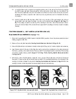
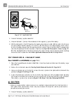
4. Turn the key switch ON, closing the circuit. The oil light should illuminate. If the low oil warning light
does not illuminate, the oil level sensor needs to be replaced. See Oil Level Sensor Removal, Sec-
tion 13, Page 13-24.
5. Fill the engine with new oil and install a new oil filter before returning the vehicle to service. See Engine