
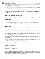


STEERING AND FRONT SUSPENSION
Rack and Pinion
Page 7-12 2001 Pioneer 900 Gasoline Vehicle Maintenance and Service Manual
7
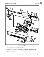
Rack and Pinion Assembly, Continued:
10. Place a few drops of Loctite
®
222 to the threads of the screw (16) (Figure 7-12, Page 7-11).
11. Install the rack guide (13), pressure spring (14), and screw (16). The screw should be threaded in until
a rotational torque of 10 in-lb (1.13 N·m) is achieved (Figure 7-12, Page 7-11).
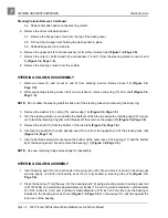
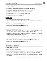
11.1. Reposition the rack and pinion in a vise.
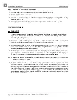
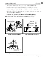
11.2. Insert a 3/8 inch deep well socket into the steering column end of the universal joint (2) and
tighten the bolt (1) to 15 ft-lb (20.3 N·m) (Figure 7-15, Page 7-12).
11.3. Use a torque wrench connected to the 3/8 inch deep well socket to measure the resistance of the
rack and pinion. Rotational resistance should measure 7 to 15 in-lb (.8 to 1.7 N·m).
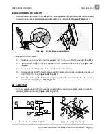
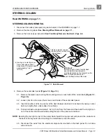
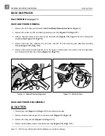
11.4. If measured resistance does not equal 7 to 15 in-lb, loosen the lock nut (15) and tighten the screw
(16) until it bottoms out, then back the screw off one quarter turn. Tighten the lock nut to 28 ft-lb
(38 N·m) (Figure 7-14, Page 7-12).
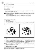
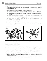
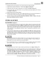
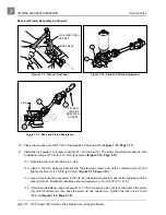
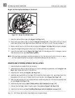
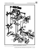
Figure 7-13 Press In Dust Seal
Figure 7-14 Rack and Pinion Adjustment
Figure 7-15 Rack and Pinion Resistance
DUST SEAL
15/16 DEEP WELL
SOCKET
16
15
2
25
VISE
3/8 INCH
1/4 DRIVE
DEEP WELL
SOCKET
1


