3-183
Cisco Broadband Cable Command Reference Guide
OL-1581-08
Chapter 3 Cisco CMTS Show Commands
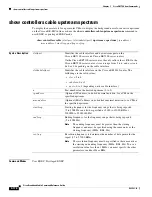
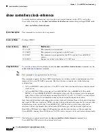
show controllers clock-reference
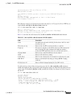
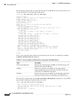
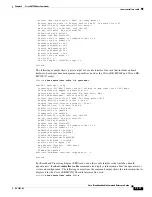
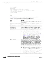
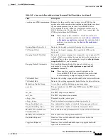
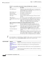
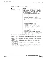
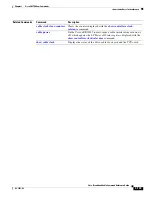
Table 3-46 show controllers clock-reference Field Descriptions
Field Description
UCPC Bus Control Status Reg
Displays the status of both TCC+ cards and of the LCD
Display Panel. Each TCC+ card displays this field from its
own point of view, where “this card” refers to itself and “the
other card” refers to the other TCC+ card slot.
•
Bits 2–0 display the status of the other TCC+ card:
–
0x00=No card.
–
0x03=The other card is the backup card.
–
0x05=The other card is the active card.
•
Bit 3 is set to 1 upon a state change for the other TCC+
card.
•
Bits 6–4 display the status of this TCC+ card:
–
0x00=No card.
–
0x03=This card is the backup card.
–
0x05=This card is the active card.
–
0x06=This card has assumed the active card role,
because the other card had been active but is now
unresponsive.
•
Bit 7 is set to 1 upon a state change for this TCC+ card.
•
Bits 13–8 are unused.
•
Bit 14 is set to 1 if the LCD Display Panel is present.
•
Bit 15 is set to 1 if the presence of the LCD Display Panel
has changed since the counters were last cleared.
The most common bit patterns for the UCPC Bus Control Status Reg field are:
•
0x4003—This TCC+ card is not present, the other card is the active card, and an LCD Display is
present.
•
0x4030—This TCC+ card is the active card, the other card is not present, and an LCD Display is
present.
•
0x4035—This TCC+ card is the backup card, the other card is the active card, and an LCD
Display is present.
•
0x4053—This TCC+ card is the active card, the other card is the backup card, and an LCD
Display is present.
•
0x4065—This TCC+ card has assumed the active card role, because the other card had been active
but is now unresponsive. The LCD Display is present.

