2-55
Cisco Broadband Cable Command Reference Guide
OL-1581-08
Chapter 2 Cisco CMTS Configuration Commands
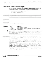
cable downstream interleave-depth
Low interleave depth values typically cause some packet loss on typical HFC networks, because burst noise
lasts beyond the error correction block correctable length. However, on cable plants with exceptionally low
noise levels, Cisco recommends initially using the default value of 32, and then trying an interleave of either
16 or 8 to see if this increases performance without increasing the number of errors that result from noise.
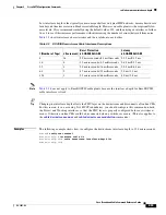
Table 2-2
shows interleave characteristics and their relation to each other.
Note
Table 2-2
does not apply to EuroDOCSIS cable plants because the interleave depth for EuroDOCSIS
cable interfaces is fixed.
Tip
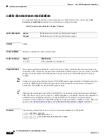
Changing the interleave depth affects the PHY layer on the downstream and disconnects all online CMs.
For this reason, if you are using N+1 HCCP redundancy, you should configure this command on both
the Protect and Working interfaces, so that the PHY layer is properly configured before a switchover
occurs. Otherwise, online CMs could be disconnected when a switchover occurs. (This also applies to
the
cable downstream annex
and
cable downstream modulation
commands.)
Examples
The following example shows how to configure the downstream interleave depth to 128 microseconds:
Router#
configure terminal
Router(config)#
interface cable 3/0
Router(config-if)#
cable downstream interleave-depth 128
Router(config-if)#
Table 2-2
DOCSIS Downstream Cable Interleave Descriptions
I (Number of Taps)
J (Increment)
Burst Protection
64-QAM/256 QAM
Latency
64-QAM/256 QAM
8
16
5.9 microseconds/4.1 milliseconds 0.22 ms/0.15 ms
16
8
12 microseconds/8.2 milliseconds
0.48 ms/0.33 ms
32
4
24 microseconds/16 milliseconds
0.98 ms/0.68 ms
64
2
47 microseconds/33 milliseconds
2.0 ms/1.4 ms
128
1
95 microseconds/66 milliseconds
4.0 ms/2.8 ms


