8
8
8-41
8-41
Service Mode > Details of Service Mode > #REPORT > Details
Service Mode > Details of Service Mode > #REPORT > Details
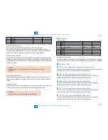
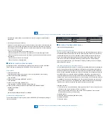
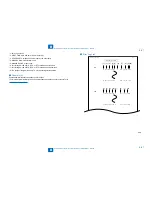
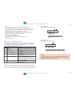
*1: service error code.
*2: START TIME, date and time (in 24-hr notation).
*3: OTHER PARTY, telephone number sent by the other party.
*4: MAKER CODE, manufacturer code.
*5: MACHINE CODE, model code.
*6: bit 1 through bit 96 of DIS, DCS, or DTC that has been received.
*7: bit 1 through bit 96 of DIS, DCS, or DTC that has been transmitted.
*8: RX, procedural signal received; TX, procedural signal transmitted.
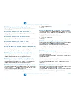
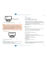
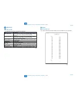
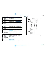
Counter List
Explanation: Maintenance/supplies counter output.
(For more detailed information about the maintenance/supplies counter output, refer to
"#COUNTER"(page 8-34).
.)
●
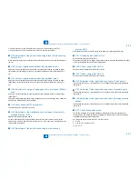
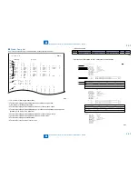
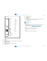
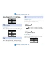
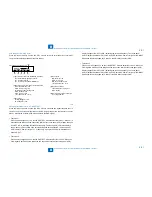
Error Log List
***************************************
*** JAM/ERR LOG REPORT ***
***************************************
07/12/2005 13:07 FAX
001
[1] [2] [3] [4] [5] [6] [7]
[8] [9] [10]
[1] [2] [3] [4] [5]
[6] [7]
[8]
JAM
01 04/12 12:17 20:03 4 1 0012 000026 1 A4
20 04/12 12:17 20:03 4 1 0012 000026 1 A4
ERR
01 04/12 12:17 15:36 3 0010 0000 000691
20 04/12 12:17 15:36 3 0010 0000 000691
●
F-8-8
F-8-8
Summary of Contents for IMAGERUNNER 2530
Page 1: ...9 8 7 6 5 4 3 2 1 imageRUNNER 2530 2525 2520 Series Service Manual...
Page 4: ...Blank Page...
Page 16: ...1 1 Product Overview Product Overview Product Lineup Feature Specifications Name of Parts...
Page 111: ...3 3 Periodical Service Periodical Service Consumable Parts and Cleaning Parts...
Page 159: ...5 5 Adjustment Adjustment Outline Adjustment when replacing parts Image position adjustment...
Page 166: ...6 6 Troubleshooting Troubleshooting Upgrading Targets and Procedure...
Page 171: ...7 7 Error Code Error Code Overview Error Code Jam Code Alarm Code...
Page 186: ...8 8 Service Mode Service Mode Outline Details of Service Mode...
Page 321: ...Service Tools General Circuit Diagram Appendix...

