9
9
9-47
9-47
Installation > Cst Heater Kit-J1 Installation Procedure > Installation Procedure
Installation > Cst Heater Kit-J1 Installation Procedure > Installation Procedure
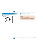
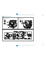
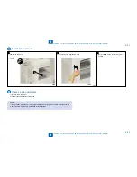
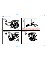
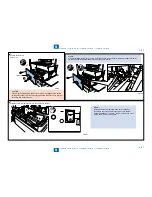
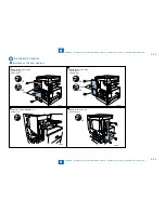
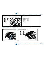
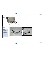
8) Remove the left cover.
Screw (1 pc.)
x1
Link Rod
CAUTION:
There is the link rod behind the left cover, which is engaged to the switch
on the power supply unit. So carefully remove the left cover not to give an
excessive lord on the link rod.
•
F-9-99
F-9-99
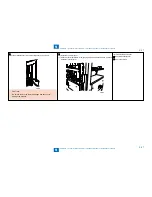
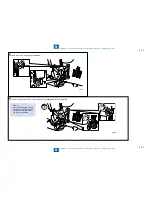
MEMO:
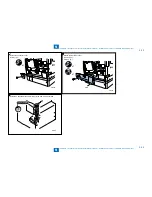
When reinstalling the left cover, surely insert the link rod in the switch on the power supply unit so the
switch does link to the main power switch of the host machine.
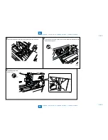
x1
x2
F-9-100
F-9-100
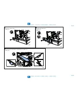
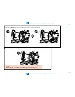
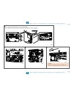
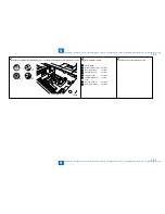
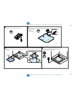
9) Install the heater SW harness firmly in the power cord bracket.
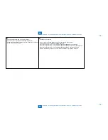
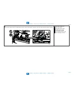
MEMO:
Install the heater SW harness in the correct direction
referring to the curved seals in the power cord bracket.
Relative positions of “I” and “O” symbol of the switch must
be the same as the curved seals.
F-9-101
F-9-101
Summary of Contents for IMAGERUNNER 2530
Page 1: ...9 8 7 6 5 4 3 2 1 imageRUNNER 2530 2525 2520 Series Service Manual...
Page 4: ...Blank Page...
Page 16: ...1 1 Product Overview Product Overview Product Lineup Feature Specifications Name of Parts...
Page 111: ...3 3 Periodical Service Periodical Service Consumable Parts and Cleaning Parts...
Page 159: ...5 5 Adjustment Adjustment Outline Adjustment when replacing parts Image position adjustment...
Page 166: ...6 6 Troubleshooting Troubleshooting Upgrading Targets and Procedure...
Page 171: ...7 7 Error Code Error Code Overview Error Code Jam Code Alarm Code...
Page 186: ...8 8 Service Mode Service Mode Outline Details of Service Mode...
Page 321: ...Service Tools General Circuit Diagram Appendix...

