9
9
9-62
9-62
Installation > Cassette Heater Unit 37 > Installation Procedure > In case of Options(Cassette Module)
Installation > Cassette Heater Unit 37 > Installation Procedure > In case of Options(Cassette Module)
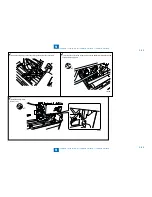
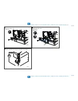
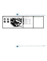
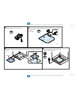
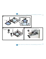
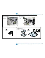
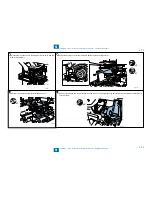
5) Install the Wire Saddle to Heater Connector Cover.
F-9-133
6) Put the connector of the heater through the Wire Saddle and install the Heater Connector Cover.
1 Screw (P tight;
M3x8)
1 Wire saddle
•
•
F-9-134
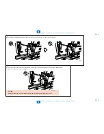
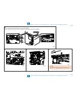
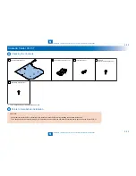
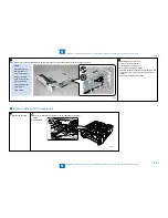
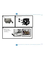
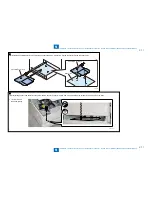
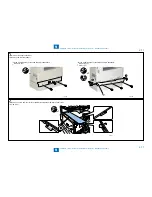
7) IInstall the Cassette Heater Unit by fitting the3 hooks to the holes .At that time, put the connector through the
square hole.
Cassette Heater Unit
Cassette Heater Unit
Base plate
F-9-135
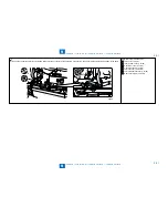
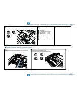
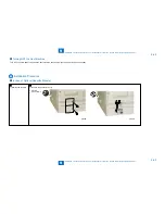
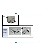
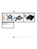
8) Connect the cassette heater unit with the stubby driver.
1 Screw (W sems round end; M3x6)
•
F-9-136
Summary of Contents for IMAGERUNNER 2530
Page 1: ...9 8 7 6 5 4 3 2 1 imageRUNNER 2530 2525 2520 Series Service Manual...
Page 4: ...Blank Page...
Page 16: ...1 1 Product Overview Product Overview Product Lineup Feature Specifications Name of Parts...
Page 111: ...3 3 Periodical Service Periodical Service Consumable Parts and Cleaning Parts...
Page 159: ...5 5 Adjustment Adjustment Outline Adjustment when replacing parts Image position adjustment...
Page 166: ...6 6 Troubleshooting Troubleshooting Upgrading Targets and Procedure...
Page 171: ...7 7 Error Code Error Code Overview Error Code Jam Code Alarm Code...
Page 186: ...8 8 Service Mode Service Mode Outline Details of Service Mode...
Page 321: ...Service Tools General Circuit Diagram Appendix...

