7
7
7-3
7-3
Error Code > Error Code > Error Code Details
Error Code > Error Code > Error Code Details
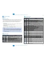
Error Code
Error Code Details
Ecode
Detail
Code
Item
Description
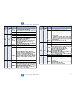
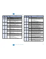
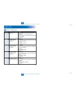
E000
0001
Title
Fixing temperature abnormal rise
Description
The temperature detected by the main thermistor does not
rise to the specified value during startup control.
Remedy
1.Go through the following to clear the error: CLEAR >
ENGIN > ERRCLR; and then turn OFF and then ON the
power.
2.Check connection of the Connectors (Thermistor Connector
and AC Connector).
3.Replace the Fixing Main Thermistor (Film Unit).
4.Replace the Fixing Assembly.
5.Replace the DC Controller PCB (PCB4).
E001
0000
Title
Fixing unit temperature rise detection
Description
The reading of the main thermistor is 250 deg C or more
continuously for 200 msec.
Remedy
1.Go through the following to clear the error: CLEAR >
ENGIN > ERRCLR; and then turn OFF and then ON the
power.
2.Check connection of the Connectors (Thermistor Connector
and AC Connector).
3.Replace the Fixing Main Thermistor (Film Unit).
4.Replace the Fixing Assembly.
5.Replace the DC Controller PCB (PCB4).
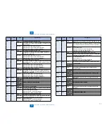
E001
0001
Title
Fixing unit temperature rise detection
Description
The hardware circuit detects overheating of the main or sub
thermistor for 200 msec.
Remedy
1.Go through the following to clear the error: CLEAR >
ENGIN > ERRCLR; and then turn OFF and then ON the
power.
2.Replace the DC Controller PCB (PCB4).
E001
0002
Title
Fixing unit temperature rise detection
Description
The reading of the sub thermistor is 295 deg C or more
continuously for 200 msec.
Remedy
1.Go through the following to clear the error: CLEAR >
ENGIN > ERRCLR; and then turn OFF and then ON the
power.
2.Check connection of the Connectors (Thermistor Connector
and AC Connector).
3.Replace the Fixing Main Thermistor (Film Unit).
4.Replace the Fixing Assembly.
5.Replace the DC Controller PCB (PCB4).
Ecode
Detail
Code
Item
Description
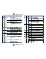
E002
0000
Title
Fixing unit temperature insufficient rise
Description
1.The reading of the main thermistor is less than 115 deg C
continuously for 400 msec 1.3 sec after it has indicated 100
deg C.
2.The reading of the main thermistor is less than 150 deg C
continuously for 400 msec 1.3 sec after it has indicated 140
deg C.
Remedy
1.Go through the following to clear the error: CLEAR >
ENGIN > ERRCLR; and then turn OFF and then ON the
power.
2.Check connection of the Connectors (Thermistor Connector
and AC Connector).
3.Replace the Fixing Main Thermistor (Film Unit).
4.Replace the Fixing Assembly.
5.Replace the DC Controller PCB (PCB4).
E003
0000
Title
Low fixing temperature detection after standby
Description
The reading of the main thermistor is less than 140 deg C
continuously for 400 msec or more.
Remedy
1.Go through the following to clear the error: CLEAR >
ENGIN > ERRCLR; and then turn OFF and then ON the
power.
2.Check connection of the Connectors (Thermistor Connector
and AC Connector).
3.Replace the Fixing Main Thermistor (Film Unit).
4.Replace the Fixing Assembly.
5.Replace the DC Controller PCB (PCB4).
E004
0000
Title
Thermistor disconnection detection error
Description
When disconnection is detected with connector (J214) for 30
sec continuously.
Remedy
1.Check connection of the Connector (J214).
2.Replace the Film Unit.
3.Replace the Fixing Assembly.
4.Replace the DC Controller PCB (PCB4).
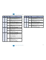
E010
0001
Title
Unstable rotation of the Main Motor (M1)
Description
Detection is executed every 100 msec after the start of motor
rotation; however, the drive detection signal is absent for 2
sec.
Remedy
1.Replace the Main Motor (M1).
2.Replace the DC Controller PCB (PCB4).
E010
0002
Title
Unstable rotation of the Main Motor (M1)
Description
During motor rotation, detection is executed every 100 msec;
however, the drive signal is absent 5 times in sequence.
Remedy
1.Replace the Main Motor (M1).
2.Replace the DC Controller PCB (PCB4).
Summary of Contents for IMAGERUNNER 2530
Page 1: ...9 8 7 6 5 4 3 2 1 imageRUNNER 2530 2525 2520 Series Service Manual...
Page 4: ...Blank Page...
Page 16: ...1 1 Product Overview Product Overview Product Lineup Feature Specifications Name of Parts...
Page 111: ...3 3 Periodical Service Periodical Service Consumable Parts and Cleaning Parts...
Page 159: ...5 5 Adjustment Adjustment Outline Adjustment when replacing parts Image position adjustment...
Page 166: ...6 6 Troubleshooting Troubleshooting Upgrading Targets and Procedure...
Page 171: ...7 7 Error Code Error Code Overview Error Code Jam Code Alarm Code...
Page 186: ...8 8 Service Mode Service Mode Outline Details of Service Mode...
Page 321: ...Service Tools General Circuit Diagram Appendix...


