8
8
8-47
8-47
Service Mode > Details of Service Mode > #TEST MODE > Details
Service Mode > Details of Service Mode > #TEST MODE > Details
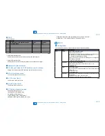
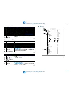
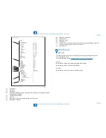
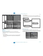
Procedure
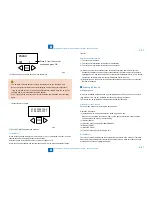
1) Enter the PG number with numeric keys, then press the START key.
2) Select single-sided (SGL: 0) or double-sided (DBL: 1), then press the START key.
3) Enter the number of prints to be output (PG COUNT), then press the START key.
4) Specify the paper drawer (main unit), then press the START key.
Main unit cassette (ST_C: 0), 2nd cassette (OP_C: 1), Manual feed tray (MLT: 2)
5) Specify the paper eject slot, then press the START key.
Tray 1 (1_OUT: 0), Tray2 (2_OUT: 1)
6) Select a paper type, then press the OK key.
Plain paper (PLN: 0), Thick paper (TCK: 1),Thin paper (OHP: 2)
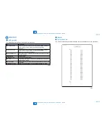
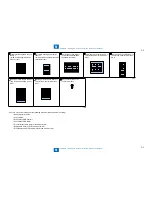
7) A test pattern is output.
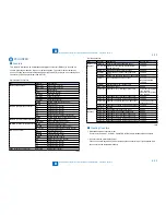
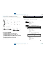
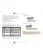
MODEM Test
<
(4) MODEM TEST>
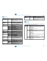
These tests test modem and NCU transmission and reception. The modem tests check
whether signals are sent correctly from the modem by comparing the sound of the signals
from the speaker with the sounds from a normal modem.
End this test by pressing the Stop key.
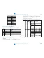
Keypad Type
Description
1
Relay Test
Use it to turn on/off a selected relay to execute a switch-
over test.
2
Frequency test
The modem sends tonal signals from the modular jack
and the speaker.
4
G3 signal transmission test
The modem sends G3 signals from the modular jack
and the speaker.
5
DTMF signal reception test
Use it to generate the DTMF signal coming from the
modem using the
telephone line terminal and the speaker.
6
Tonal signal reception test
Use it to monitor a specific frequency and the DTMF
signal received from the telephone line terminal by
causing them to be indicated on the LCD (i.e., the
presence/absence as detected). The reception signal is
generated by the speaker.
8
V.34 G3 signal transmission test The modem sends V.34 G3 signals from the modular
jack and the speaker.
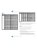
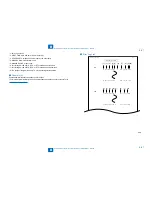
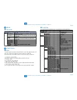
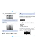
Relay Test
Press '1'or '2' on the keypad on the Modem test menu to select relay test mode. Use the
keypad to operate the various relays of the NCU. '2' on the keypad is used for 230V machine.
●
T-8-59
Numeric keypad key 1
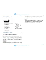
The input key and relay are shown below:
RELAY TEST1 OFF OFF
OFF OFF OFF OFF
[1] [2] [3] [4] [5] [6]
Relay
CML P S H D R
Keypad
0
1 2 3 4 5
[1]
[2]
[3]
[4] [5]
[6]
Numeric keypad key 2
The input key and relay are shown below:
RELAY TEST2 OFF OFF
OFF OFF OFF OFF OFF
[1] [2] [3] [4] [5] [6] [7]
Relay
CITS2 C1 NORG DCSEL DCLIM IPSEL1 IPSEL2
Keypad 0 1
2 3 4 5 6
[1]
[2]
[3]
[4] [5]
[6]
[7]
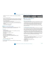
CAUTION:
The touch panel (LCD) is turned on or off in relation to the transmission of the relay
operation signal as is operated on the keypad; for this reason, you cannot use the
touch panel (LCD) to check a fault on a single relay.
•
•
F-8-12
F-8-13
Summary of Contents for IMAGERUNNER 2530
Page 1: ...9 8 7 6 5 4 3 2 1 imageRUNNER 2530 2525 2520 Series Service Manual...
Page 4: ...Blank Page...
Page 16: ...1 1 Product Overview Product Overview Product Lineup Feature Specifications Name of Parts...
Page 111: ...3 3 Periodical Service Periodical Service Consumable Parts and Cleaning Parts...
Page 159: ...5 5 Adjustment Adjustment Outline Adjustment when replacing parts Image position adjustment...
Page 166: ...6 6 Troubleshooting Troubleshooting Upgrading Targets and Procedure...
Page 171: ...7 7 Error Code Error Code Overview Error Code Jam Code Alarm Code...
Page 186: ...8 8 Service Mode Service Mode Outline Details of Service Mode...
Page 321: ...Service Tools General Circuit Diagram Appendix...

