5
5
5-6
5-6
Adjustment > Image position adjustment > Leading Edge Non-Image Width
Adjustment > Image position adjustment > Leading Edge Non-Image Width
Image position adjustment
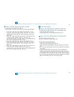
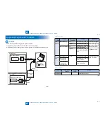
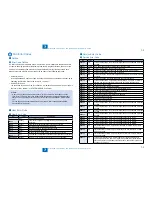
Copy 10 sheets from each pickup position to check that the image margin and non-image
area is within the standard.
Each cassette
Pickup tray
If it is not within the standard, go through the following procedures to adjust it.
CAUTION:
If changing the value of service mode item in this adjustment, enter the changed value
in the service label.
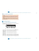
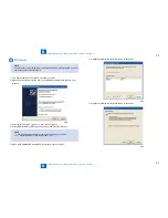
Margin Along the Leading Edge
Service mode> PRINT> PRINT NUMERIC> 053
2
5
4 6 8 10 12 14 16 18 20
0
Paper
leading edge
Decrease the value.
(a decrease of '10' will
increase the margin by 1 mm)
Increase the value.
(an increase of '10' will
increase the margin by 1 mm)
1st side of copy: 2.5+/-1.5mm
•
•
F-5-3
F-5-3
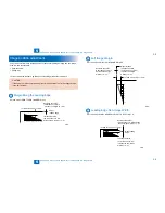
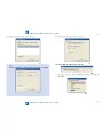
Left Image Margin
Service mode> PRINT> PRINT NUMERIC> 056
10
8
6
5
4
2
0
1st side of copy: 2.5+/-1.5mm
Image left edge
Increase the value.
(an increase of '10' will
increase the margin
width by 1 mm)
Decrease the value.
(a decrease of '10' will
decrease the margin
width by 1 mm)
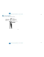
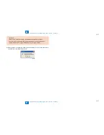
Leading Edge Non-Image Width
Service mode> SCAN> READER> ADJUST> ADJ-XY> ADJ-X
2 5
4 6 8 1012141618 20
0
1st side of copy: 2.5+/-1.5mm
Image leading
edge
Decrease the value.
(a decrease of '10' will decrease
the non-image width by 1 mm)
Increase the value.
(an increase of '10' will
increase the non-image
width by 1 mm)
F-5-4
F-5-4
F-5-5
F-5-5
Summary of Contents for IMAGERUNNER 2530
Page 1: ...9 8 7 6 5 4 3 2 1 imageRUNNER 2530 2525 2520 Series Service Manual...
Page 4: ...Blank Page...
Page 16: ...1 1 Product Overview Product Overview Product Lineup Feature Specifications Name of Parts...
Page 111: ...3 3 Periodical Service Periodical Service Consumable Parts and Cleaning Parts...
Page 159: ...5 5 Adjustment Adjustment Outline Adjustment when replacing parts Image position adjustment...
Page 166: ...6 6 Troubleshooting Troubleshooting Upgrading Targets and Procedure...
Page 171: ...7 7 Error Code Error Code Overview Error Code Jam Code Alarm Code...
Page 186: ...8 8 Service Mode Service Mode Outline Details of Service Mode...
Page 321: ...Service Tools General Circuit Diagram Appendix...

