4
4
4-41
4-41
Parts Replacement and Cleaning > PCB > Removing the Main Controller PCB > Action to Take after Replacement
Parts Replacement and Cleaning > PCB > Removing the Main Controller PCB > Action to Take after Replacement
PCB
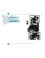
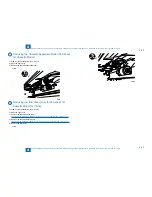
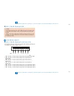
Removing the DC Controller PCB
Before Replacement/RAM Clearing
Print the service data list in the service mode.
REPORT > REPORT OUTPUT > SERVICE DATA LIST
Replacement Procedure
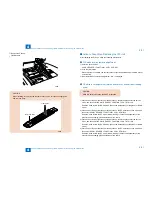
1) Remove the rear cover (right). (
"Removing the Rear Cover (Right)"(page 4-20)..
)
2) Remove the rear cover (left). (
"Removing the Rear Cover (Left)"(page 4-21)
..
)
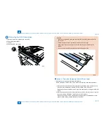
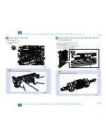
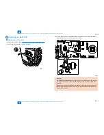
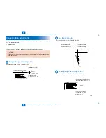
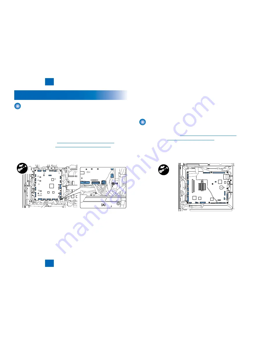
3) Disconnect all connectors on the DC controller PCB.
4) Remove the DC controller PCB.
- 6 screws (Screw A is tightened together with the earth cable.)
x6
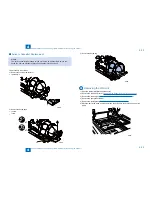
Action to Take after Replacement/RAM Clearing
1) Clear the DC controller settings and counters.
Enter the service mode, and Then select the following:
CLEAR > ENGINE > ENGINE BKRAMCLK (Clearing of the RAM on the DC controller
PCB)
2) Turn OFF and then ON the main power switch. (Turning OFF/ON the main power switch
clears the RAM.)
3) If uploading of backup data fails before replacement due to the damage to the DC
controller PCB, enter the values of service mode items recorded on the service label.
■
■
■
F-4-93
F-4-93
Since the values recorded on the service label may be outdated, check the service mode
item list (#SERVICE DATA LIST) printed out in advance, and then enter the latest values.
4) Turn OFF and then ON the main power switch. (Turning OFF/ON the main power switch
allows the values entered for the service mode items to take effect.)
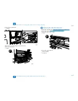
Removing the Main Controller PCB
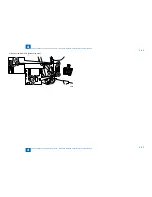
Replacement Procedure
1) Remove the left cover (right).(
"Removing the Rear Cover (Right)"(page 4-20).
)
2) Remove the RAM.(
"Removing the RAM PCB"(page 4-42).)
3) Remove the modem PCB (for the model with a FAX function).
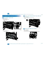
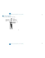
4) Disconnect all connectors and flexible cables on the main controller PCB.
5) Remove the main controller PCB.
- 9 screws
x9
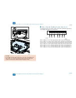
Action to Take after Replacement
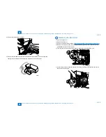
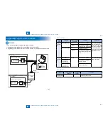
After replacing the image processor PCB with a new one, take the following action:
- Download the latest firmware with the UST.
- Enter all values recorded on the service label affixed to the rear cover.
■
■
F-4-94
F-4-94
Summary of Contents for IMAGERUNNER 2530
Page 1: ...9 8 7 6 5 4 3 2 1 imageRUNNER 2530 2525 2520 Series Service Manual...
Page 4: ...Blank Page...
Page 16: ...1 1 Product Overview Product Overview Product Lineup Feature Specifications Name of Parts...
Page 111: ...3 3 Periodical Service Periodical Service Consumable Parts and Cleaning Parts...
Page 159: ...5 5 Adjustment Adjustment Outline Adjustment when replacing parts Image position adjustment...
Page 166: ...6 6 Troubleshooting Troubleshooting Upgrading Targets and Procedure...
Page 171: ...7 7 Error Code Error Code Overview Error Code Jam Code Alarm Code...
Page 186: ...8 8 Service Mode Service Mode Outline Details of Service Mode...
Page 321: ...Service Tools General Circuit Diagram Appendix...

