5
5
5-3
5-3
Adjustment > Adjustment when replacing parts > Scanning System > Action to Take after Replacing the Platen Glass
Adjustment > Adjustment when replacing parts > Scanning System > Action to Take after Replacing the Platen Glass
Adjustment when replacing parts
Scanning System
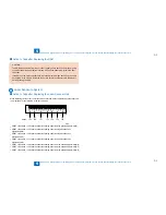
Action to Take after Replacing the CIS Unit
After replacing the CIS unit, make the following adjustments:
CIS white level automatic adjustment
1) Enter the service mode.
SCAN > READER > FUNCTION > CCD > CCD-ADJ
2) Click the [OK] button.
When this step is complete, the contact sensor output is adjusted and parameters are set
automatically.
3) After completion of automatic adjustment, “OK” is displayed.
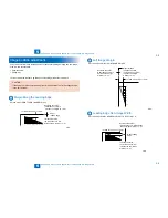
DF white level adjustment (platen board cover scan/stream reading
scan)
CAUTION:
Make this adjustment when the DADF is installed.
1) Place a sheet of paper that the user usually uses on the platen glass, enter the service
mode, and then select SCAN > READER > FUNCTION > CCD > DFWLVL1.
Read the white level in the BOOK mode. (Check the transparency of the glass for BOOK
mode.)
2) Place a sheet of paper that the user usually uses on the DF, enter the service mode, and
then select SCAN > READER > FUNCTION > CCD > DF-WLVL2.
Read the white level in the DF mode (stream reading). (Check the transparency of the
glass for stream reading.)(Read both sides of the chart.)
3) Place a sheet of paper that the user usually uses on the platen glass, enter the service
mode, and then select SCAN > READER > FUNCTION > CCD > DFWLVL3.
Read the white level in the BOOK mode. (Check the transparency of the glass for BOOK
mode.)
4) Place a sheet of paper that the user usually uses on the DF, enter the service mode, and
then select SCAN > READER > FUNCTION > CCD > DF-WLVL4.
Read the white level in the DF mode (stream reading). (Check the transparency of the
■
●
●
glass for stream reading.)(Read both sides of the chart.)
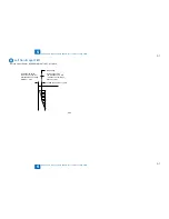
Action to Take after Replacing the Platen Glass
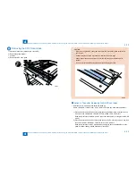
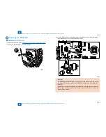
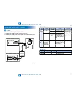
CAUTION:
Be sure to make the white plate data adjustment before ADF white level
adjustment.
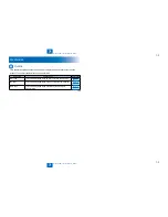
W-PLT-X
W-PLT-Y
W-PLT-Z
F-5-1
F-5-1
1.Enter the value indicated on the platen glass in the following service mode:
SCAN > READER > ADJUST > CCD > W-PLT-X/Y/Z (Input of standard white plate data)
2.Enter the service mode, and then select the following:
SCAN > READER > FUNCTION > CCD > DF-WLVL1/2/3/4 (DF white level adjustment)
1) Place a sheet of paper that the user usually uses on the platen glass, enter the
service mode, and then select SCAN > READER > FUNCTION > CCD > DFWLVL1.
Read the white level in the BOOK mode. (Check the transparency of the glass for
BOOK mode.)
2) Place a sheet of paper that the user usually uses on the DF, enter the service mode,
and then select SCAN > READER > FUNCTION > CCD > DF-WLVL2.
Read the white level in the DF mode (stream reading). (Check the transparency of the
glass for stream reading.)(Read both sides of the chart.)
3) Place a sheet of paper that the user usually uses on the platen glass, enter the
service mode, and then select SCAN > READER > FUNCTION > CCD > DFWLVL3.
Read the white level in the BOOK mode. (Check the transparency of the glass for
BOOK mode.)
4) Place a sheet of paper that the user usually uses on the DF, enter the service mode,
and then select SCAN > READER > FUNCTION > CCD > DF-WLVL4.
Read the white level in the DF mode (stream reading). (Check the transparency of the
glass for stream reading.)(Read both sides of the chart.)
■
Summary of Contents for IMAGERUNNER 2530
Page 1: ...9 8 7 6 5 4 3 2 1 imageRUNNER 2530 2525 2520 Series Service Manual...
Page 4: ...Blank Page...
Page 16: ...1 1 Product Overview Product Overview Product Lineup Feature Specifications Name of Parts...
Page 111: ...3 3 Periodical Service Periodical Service Consumable Parts and Cleaning Parts...
Page 159: ...5 5 Adjustment Adjustment Outline Adjustment when replacing parts Image position adjustment...
Page 166: ...6 6 Troubleshooting Troubleshooting Upgrading Targets and Procedure...
Page 171: ...7 7 Error Code Error Code Overview Error Code Jam Code Alarm Code...
Page 186: ...8 8 Service Mode Service Mode Outline Details of Service Mode...
Page 321: ...Service Tools General Circuit Diagram Appendix...


