8
8
8-29
8-29
Service Mode > Details of Service Mode > #PRINT > List of Functions
Service Mode > Details of Service Mode > #PRINT > List of Functions
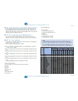
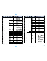
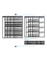
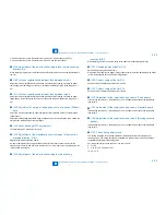
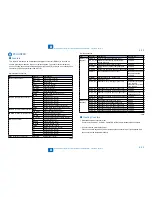
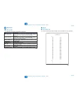
2. Fixed environment of NN. (Temperature of 18-28 deg C and humidity of 20-75%)
3. Fixed environment of HH. (Temperature of 28 deg C and humidity of 80%)
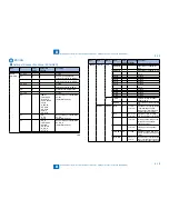
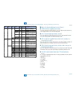
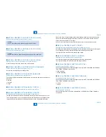
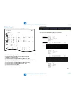
<136: Adjustment of the point to start writing in laser's main scanning
direction (A)>
When replacing the laser unit, enter the unit-specific delay value shown on the label affixed to
the unit.
<140: Left-end registration adjustment (double-sided small) >
Adjust the left-end registration margin needed when the duplex feeding unit picks up paper
(small paper). Incrementing the value by 1 increases the left-end margin of the image by 0.1
mm.
<141: Left-end registration adjustment (double-sided large)>
Adjust the left-end registration margin needed when the duplex feeding unit picks up paper
(large paper). Incrementing the value by 1 increases the left-end margin of the image by 0.1
mm.
<142: Adjustment of margin at leading edge at normal speed (230mm/
sec)>
Adjust the margin at the leading edge (registration roller clutch ON timing) at normal speed
(230mm/sec).
Adjust the leading-edge registration margin needed at pickup. Increasing the value makes the
margin at the leading edge of the copy larger.
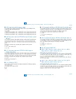
<144: Laser trail edge OFF adjustment>
Laser trail edge OFF adjustment input only.
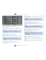
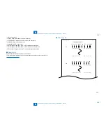
<145: Adjustment of the magnification to write image in laser's main
scanning direction (A-B)>
Magnification between lasers A and B.
Amount of adjustment of the magnification of laser B of the laser scanner unit. Adjust the
magnification of laser B with reference to that of laser A. If the input value is inappropriate, the
image quality is degraded.
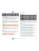
<148: Adjustment of the point to start writing in main scanning
●
●
●
●
●
●
●
direction (A-B)>
When replacing the laser, enter the delay value (laser main scanning adjustment).
<151: Developing bias offset for DC>
Enter the developing bias offset for DC.
When a fault in image occurs (foggy image or light density), enter the developing bias offset
for DC. Increasing the value makes the image darker.
<152: Primary charge offset for DC>
Enter the value to adjust the primary offset 1 for DC.
<153: Primary charge offset for AC>
Enter the value to adjust the primary offset 1 for AC.
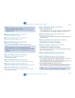
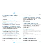
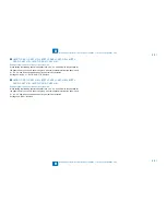
<154: Adjustment of the registration loop volume (Thick paper)>
Incrementing the value by 1 feeds the paper 0.1 mm further and increases the registration
loop volume.
<155: Adjustment of the registration loop volume (Special paper)>
Incrementing the value by 1 feeds the paper 0.1 mm further and increases the registration
loop volume.
<156: Adjustment of the registration loop volume (Envelop cassette
pickup)>
Incrementing the value by 1 feeds the paper 0.1 mm further and increases the registration
loop volume.
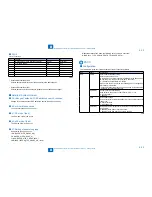
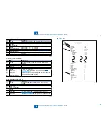
<157: Pickup timing adjustment>
This setting is applied to the pickup permission temperature at job start irrespective of
the fixing mode. The pickup permission temperature is raised or lowered from the default
temperature according to the setting value.
Use this parameter to reduce the FCOT or warm-up time.
0 - 2:+15˚C
3 - 11:12 to -15˚C (in steps of 3˚C)
12 - 14: -15˚C
●
●
●
●
●
●
●
Summary of Contents for IMAGERUNNER 2530
Page 1: ...9 8 7 6 5 4 3 2 1 imageRUNNER 2530 2525 2520 Series Service Manual...
Page 4: ...Blank Page...
Page 16: ...1 1 Product Overview Product Overview Product Lineup Feature Specifications Name of Parts...
Page 111: ...3 3 Periodical Service Periodical Service Consumable Parts and Cleaning Parts...
Page 159: ...5 5 Adjustment Adjustment Outline Adjustment when replacing parts Image position adjustment...
Page 166: ...6 6 Troubleshooting Troubleshooting Upgrading Targets and Procedure...
Page 171: ...7 7 Error Code Error Code Overview Error Code Jam Code Alarm Code...
Page 186: ...8 8 Service Mode Service Mode Outline Details of Service Mode...
Page 321: ...Service Tools General Circuit Diagram Appendix...

