2
2
2-47
2-47
Technology > Fixing System > Controls > Print temperature control
Technology > Fixing System > Controls > Print temperature control
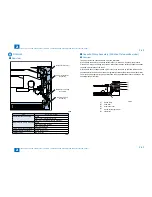
C.Sheet-to-sheet distance temperature control
To prevent the excessive temperature rise and to save the power consumption, the
target temperature is set 5 deg C low (in case of plain paper *1) from the printing
temperature.
*1. Set to 5, 15 or 20 deg C low according paper type
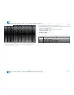
Target temperature during printing
The control temperature is determined according to the fixing mode or to the fixing
temperature at the start of warm-up control. The 12 modes are provided as the fixing mode
for the selected feed table and paper type.
The following table is the control temperature when the fixing temperature is less than 55
deg C at the start of warm-up control.
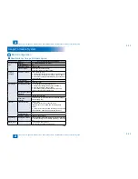
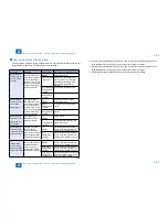
Fixing mode
Setting
Target temperature (deg C)
1-sided/first of 2-sided
Second of 2-sided
Plain paper
Paper type
208
203
Thin paper
198
193
S-thin paper
188
183
Heavy paper
223
223
Heavy paper-H
223
223
Bond paper
23
223
OHP
198
198
Postcard
223
---
S-Postcard
223
---
Envelope
223
---
N1
165
165
N3
155
155
Related Service Mode
Offset of fixing control temperature (High and low of control temperature)
PRINT > SW
> 62 (Control temperature during cassette feeding)
> 63 (Control temperature in Heavy/Heavy-H/Bond paper modes)
> 166 (Control temperature for the second side of 2-sided copying)
> 173 (Control temperature for the second side of 2-sided copying)
> 179 (Control temperature in Postcard/S-Postcard/Envelope modes)
<Setting value>
0 to 2: +15 deg C
3 to 11: +12 to -15 deg C (each 3 deg C) [Default: 7]
12 to 14: -15 deg C
T-2-25
T-2-25
Summary of Contents for IMAGERUNNER 2530
Page 1: ...9 8 7 6 5 4 3 2 1 imageRUNNER 2530 2525 2520 Series Service Manual...
Page 4: ...Blank Page...
Page 16: ...1 1 Product Overview Product Overview Product Lineup Feature Specifications Name of Parts...
Page 111: ...3 3 Periodical Service Periodical Service Consumable Parts and Cleaning Parts...
Page 159: ...5 5 Adjustment Adjustment Outline Adjustment when replacing parts Image position adjustment...
Page 166: ...6 6 Troubleshooting Troubleshooting Upgrading Targets and Procedure...
Page 171: ...7 7 Error Code Error Code Overview Error Code Jam Code Alarm Code...
Page 186: ...8 8 Service Mode Service Mode Outline Details of Service Mode...
Page 321: ...Service Tools General Circuit Diagram Appendix...

