9
9
9-52
9-52
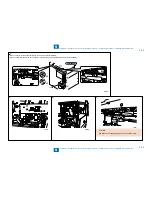
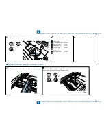
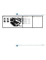
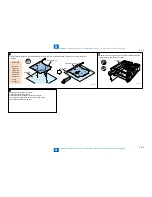
Installation > Reader Heater Unit-H1 Installation Procedure > Points to Note Before Installation > Confirmation of Heater Driver PCB
Installation > Reader Heater Unit-H1 Installation Procedure > Points to Note Before Installation > Confirmation of Heater Driver PCB
Reader Heater Unit-H1 Installation Procedure
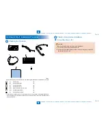
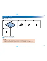
Checking the Contents
[1]
[3]
[4]
[5]
[2]
<For 230V model>
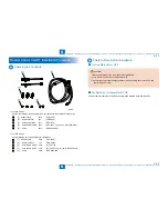
Confirm the following components with correct quantities are contained in the carton.
[1]
Reader heater
2pcs.
(FK2-0228)
[2]
Heater harness
1pc.
(FM4-2929)
[3]
Wire saddle (large) 3pcs.
(WT2-5719)
[4]
Wire saddle (small) 3pcs.
(WT2-0507, only for use in iR-2545/2535)
[5]
Screw
2pcs.
(XB2-8400-609)
<For 120V model>
Get the following service parts ready for installation.
[1]
Reader heater
2pcs.
(FK2-9468)
[2]
Heater harness
1pc.
(FM4-2929)
[3]
Wire saddle (large) 3pcs.
(WT2-5719)
[4]
Wire saddle (small) 3pcs.
(WT2-0507, only for use in iR-2545/2535)
[5]
Screw
2pcs.
(XB2-8400-609)
F-9-110
F-9-110
Points to Note Before Installation
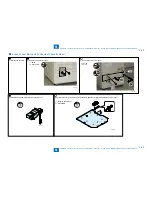
Turning Main Power OFF
CAUTION
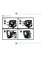
Perform the following in the order prior to the installation.
1) Turn the main power of the host machine OFF.
2) Confirm the control panel display and the main power lamp have turned OFF and
unplug the power cord.
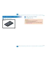
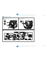
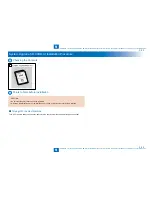
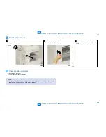
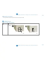
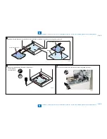
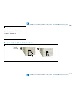
Confirmation of Heater Driver PCB
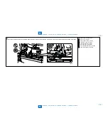
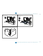
Confirm that the heater driver PCB has already been installed in the host machine.
■
■
Summary of Contents for IMAGERUNNER 2530
Page 1: ...9 8 7 6 5 4 3 2 1 imageRUNNER 2530 2525 2520 Series Service Manual...
Page 4: ...Blank Page...
Page 16: ...1 1 Product Overview Product Overview Product Lineup Feature Specifications Name of Parts...
Page 111: ...3 3 Periodical Service Periodical Service Consumable Parts and Cleaning Parts...
Page 159: ...5 5 Adjustment Adjustment Outline Adjustment when replacing parts Image position adjustment...
Page 166: ...6 6 Troubleshooting Troubleshooting Upgrading Targets and Procedure...
Page 171: ...7 7 Error Code Error Code Overview Error Code Jam Code Alarm Code...
Page 186: ...8 8 Service Mode Service Mode Outline Details of Service Mode...
Page 321: ...Service Tools General Circuit Diagram Appendix...

