1
1
1-3
1-3
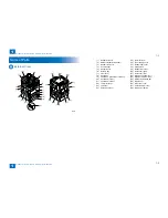
Product Overview > Product Lineup > Option > Pickup delivery / image reading options
Product Overview > Product Lineup > Option > Pickup delivery / image reading options
Option
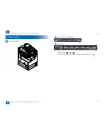
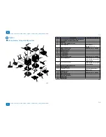
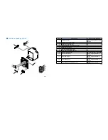
Pickup delivery / image reading options
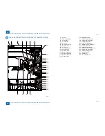
[4]
[2]
[1]
[3]
[5]
[6]
[7]
[8]
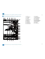
[11]
[9]
[10]
[12]
[13]
[14]
[15]
[16]
[17]
[18]
[20]
[19]
[21]
[22]
[23]
■
F-1-3
F-1-3
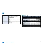
No.
Product name
Remarks and condition
1
imageRUNNER 2530i/2530/2525i/2525/2520i/2520
2
imageRUNNER 2530i/2530/2525i/2525
3
DADF-AB1
4
Inner Finisher Additional Tray-B1
5
Inner Finisher-B1
Built-in finisher
Power Supply Unit-U1 is
required.
6
Reader Heater Unit-H1
Cst Heater Kit-J1 is required.
7
Platen Cover Type P
8
Document Tray-J1
9
FL Cassette-AJ1
10
FL Cassette-AK1
11
FL Cassette-AL1
12
Cassette Heater Unit-37
Cst Heater Kit-J1 is required.
13
Cassette Module-W1
Cassette Spacer-A1 is required
when installing to 250 Sheets
Cassette Model.
14
CST. Feeding Unit-AE1
Cassette Spacer-A1 is required
when installing to 250 Sheets
Cassette Model.
15
Envelope Feeder Attachment-D1
16
Cassette Spacer-A1
17
Inner 2Way Tray-G1
For host machine delivery
additional tray.
18
Cst Heater Kit-J1
19
Drum Heater-C1
Cst Heater Kit-J1 is required.
20
Power Supply Unit-U1
21
ADF Access Handle-A1
22
2 Way Unit-B1
23
Stamp Unit-B1
T-1-3
T-1-3
Summary of Contents for IMAGERUNNER 2530
Page 1: ...9 8 7 6 5 4 3 2 1 imageRUNNER 2530 2525 2520 Series Service Manual...
Page 4: ...Blank Page...
Page 16: ...1 1 Product Overview Product Overview Product Lineup Feature Specifications Name of Parts...
Page 111: ...3 3 Periodical Service Periodical Service Consumable Parts and Cleaning Parts...
Page 159: ...5 5 Adjustment Adjustment Outline Adjustment when replacing parts Image position adjustment...
Page 166: ...6 6 Troubleshooting Troubleshooting Upgrading Targets and Procedure...
Page 171: ...7 7 Error Code Error Code Overview Error Code Jam Code Alarm Code...
Page 186: ...8 8 Service Mode Service Mode Outline Details of Service Mode...
Page 321: ...Service Tools General Circuit Diagram Appendix...


