2
2
2-51
2-51
Technology > Fixing System > Controls > Paper loop amount control before fixing
Technology > Fixing System > Controls > Paper loop amount control before fixing
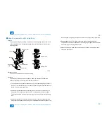
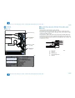
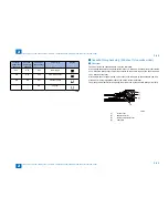
Paper loop amount control before fixing
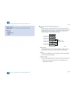
Purpose:
To get a proper image by avoiding a shock when the trailing edge of paper comes out
of the registration roles, an appropriate paper loop is formed between transfer roller
and fixing roller.
Pressure roller
Fixing film
Drum
Loop sensor(S6)
Transfer roller
Registration
roller
Sensor: OFF
Sensor: ON
Starting conditions:
This control is performed at every paper feeding.
Operation:
The fixing motor drive speed is controlled as follows by detecting the paper loop
between transfer roller and fixing roller with the loop sensor.
1) The fixing motor drive speed is reduced by 3.1% when the reading edge of paper is
fed 35mm from the transfer roller. The reduced speed is kept until the loop sensor is
turned on by the formed paper loop.
2) After detecting the ON condition of the loop sensor for 50 msec continuously, the
fixing motor drive speed is increased by 0.8% compared with the process speed.
The increased speed is kept until the loop sensor is turned off by the deleted paper
loop.
3) After detecting the OFF condition of the loop sensor for 50 msec continuously, the
fixing motor drive speed is reduced by 3.1% compared with the process speed. The
■
F-2-75
F-2-75
reduced speed is kept until the loop sensor is turned on by the formed paper loop.
4) Repeat steps 2) and 3). The fixing motor drive speed is increased by 0.8%
compared with the process speed when the trailing edge of paper reaches 65 mm
before coming out of the registration roller.
5) When continuously making prints, return to step 1). When making a single print,
shift to the last rotation.
Summary of Contents for IMAGERUNNER 2530
Page 1: ...9 8 7 6 5 4 3 2 1 imageRUNNER 2530 2525 2520 Series Service Manual...
Page 4: ...Blank Page...
Page 16: ...1 1 Product Overview Product Overview Product Lineup Feature Specifications Name of Parts...
Page 111: ...3 3 Periodical Service Periodical Service Consumable Parts and Cleaning Parts...
Page 159: ...5 5 Adjustment Adjustment Outline Adjustment when replacing parts Image position adjustment...
Page 166: ...6 6 Troubleshooting Troubleshooting Upgrading Targets and Procedure...
Page 171: ...7 7 Error Code Error Code Overview Error Code Jam Code Alarm Code...
Page 186: ...8 8 Service Mode Service Mode Outline Details of Service Mode...
Page 321: ...Service Tools General Circuit Diagram Appendix...


