9
9
9-7
9-7
Installation > Making Pre-Checks > Selecting the Site of Installation
Installation > Making Pre-Checks > Selecting the Site of Installation
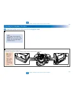
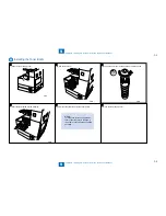
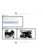
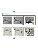
3) Remove all pieces of fixing tapes and materials.
4) For the iR2545/2535 Series, remove two optical system fixing
screws on the right side of the reader. (Keep the removed screws
because they may be used later for machine relocation.)
x2
F-9-5
F-9-5
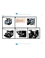
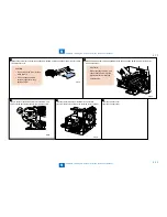
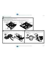
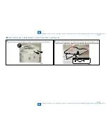
5) Press the cassette release button to draw out the cassette forward.
6) Remove the wire that secures the intermediate plate of the cassette.
<250 sheets cassette>
<550 sheets cassette>
F-9-6
F-9-6
Summary of Contents for IMAGERUNNER 2530
Page 1: ...9 8 7 6 5 4 3 2 1 imageRUNNER 2530 2525 2520 Series Service Manual...
Page 4: ...Blank Page...
Page 16: ...1 1 Product Overview Product Overview Product Lineup Feature Specifications Name of Parts...
Page 111: ...3 3 Periodical Service Periodical Service Consumable Parts and Cleaning Parts...
Page 159: ...5 5 Adjustment Adjustment Outline Adjustment when replacing parts Image position adjustment...
Page 166: ...6 6 Troubleshooting Troubleshooting Upgrading Targets and Procedure...
Page 171: ...7 7 Error Code Error Code Overview Error Code Jam Code Alarm Code...
Page 186: ...8 8 Service Mode Service Mode Outline Details of Service Mode...
Page 321: ...Service Tools General Circuit Diagram Appendix...

