


6-36
2004 Buell Lightning: Drive/Transmission
HOME
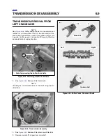
TRANSMISSION ASSEMBLY
6.10
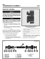
MAINSHAFT ASSEMBLY
1
1
WARNING
1
WARNING
Always wear proper eye protection when removing re-
taining rings. Use the correct retaining ring pliers. Verify
that the tips of the pliers are not damaged or excessively
worn. Slippage could propel the ring with enough force
to cause death or serious injury.
CAUTION
During assembly, the split bearings and the internal
bores of the gears must be lubricated with SPORT-
TRANS FLUID prior to assembly. Leaving these parts dry
could accelerate wear at start-up.
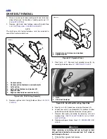
1.
See
Figure 6-65.
Install
new
retaining ring (1) onto main-
shaft in the first ring groove from the threaded end of the
mainshaft.
2.
Slide mainshaft 1st gear (2), identified by two grooves in
gear teeth, onto mainshaft with the fork groove facing
mainshaft 4th gear (10).
NOTE
See
Figure 6-64.
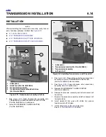
The shifting fork groove on mainshaft 1st
gear has been made 0.020 in. (0.5 mm) wider than existing
mainshaft first gear (Part No. 35762-89A) to accommodate
the new style shifting fork and has a new part number.
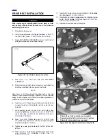
3.
See
Figure 6-65.
Install
new
retaining ring (3).
a.
Install thrust washer (4) onto mainshaft.
b.
Install split bearing (5) onto mainshaft.
c.
Install mainshaft 3rd gear (6) onto shaft over bearing
(5). 3rd gear is installed with shifting lugs away from
1st gear mainshaft.
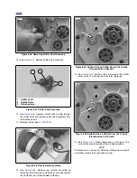
4.
Install thrust washer (7) and
new
retaining ring (8) next
to mainshaft 3rd gear (6).
5.
Install thrust washer (9) on threaded end of mainshaft
next to retaining ring (1).
6.
Install split bearing (10) onto mainshaft next to thrust
washer (9).
7.
Install mainshaft 4th gear (11), which can be identified by
the two radial grooves on one side, onto mainshaft over
split bearing (10) and against thrust washer (9).
8.
Install spacer (12) onto end of mainshaft.
Figure 6-64. New Mainshaft 1st Gear
with Identification Grooves
8757
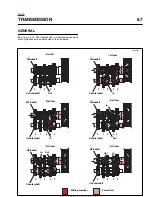
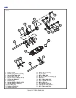
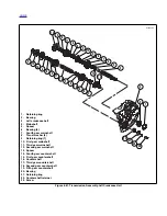
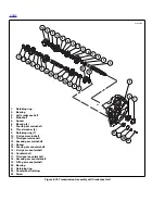
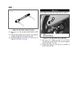
Figure 6-65. Transmission Mainshaft Assembly/Reassembly
1.
Retaining ring
2.
Mainshaft 1st
3.
Retaining ring
4.
Thrust washer
5.
Split bearing
6.
Mainshaft 3rd
7.
Thrust washer
8.
Retaining ring
9.
Thrust washer
10. Split bearing
11. Mainshaft 4th
12. Spacer
13. Mainshaft
1
3
4
5
7
8
6
2
b1019x6x
9
11
10
12
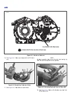
Left Crankcase
13
Summary of Contents for 2004 XB9S
Page 2: ......
Page 35: ...D 2 2004 Buell Lightning Appendix D HOME Rear Brake Systems Top View b1115xbsx ...
Page 36: ...2004 Buell Lightning Appendix D D 3 HOME Rear Brake Systems Left Side View b1116xcsx ...
Page 44: ...2004 Buell Lightning Appendix D D 11 HOME Clutch Cable Right Side View b1124xasx ...
Page 47: ...HOME NOTES ...
Page 49: ......
Page 103: ......
Page 201: ...HOME NOTES ...
Page 203: ......
Page 275: ...HOME NOTES ...
Page 307: ...HOME NOTES ...
Page 311: ...HOME NOTES ...
Page 351: ...HOME NOTES ...
Page 441: ......
Page 463: ...HOME NOTES ...
Page 465: ......
Page 517: ...HOME NOTES ...
Page 519: ......
Page 595: ...HOME NOTES ...
Page 597: ......