2004 Buell Lightning: Starter
5-9
HOME
DIAGNOSTICS/TROUBLESHOOTING
5.5
GENERAL
Follow the
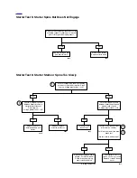
5.3 STARTING SYSTEM DIAGNOSIS
diagram to
diagnose starting system problems. The
VOLTAGE DROPS
procedure below will help you to locate poor connections or
components with excessive voltage drops.
VOLTAGE DROPS
Check the integrity of all wiring, switches, fuses and connec-
tors between the source and destination.
The voltage drop test measures the difference in potential or the
actual voltage dropped between the source and destination.
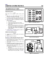
1.
See
ITEM A
in
Figure 5-3.
Attach your red meter lead to
the most positive part of the circuit, which in this case
would be the positive post of the battery (1).
2.
See
ITEM B
in
Figure 5-3.
Attach the black meter lead to
the final destination or component in the circuit (solenoid
terminal from relay).
3.
Activate the starter and observe the meter reading. The
meter will read the voltage dropped or the difference in
potential between the source and destination.
4.
An ideal circuit’s voltage drop would be 0 volts or no volt-
age dropped, meaning no difference in potential.
5.
See
ITEM C
in
Figure 5-3.
An open circuit should read
12 volts, displaying all the voltage dropped, and the
entire difference in potential displayed on the meter.
6.
Typically, a good circuit will drop less than 1 volt.
7.
If the voltage drop is greater, back track through the con-
nections until the source of the potential difference is
found. The benefit of doing it this way is speed.
a.
Readings aren’t as sensitive to real battery voltage.
b.
Readings show the actual voltage dropped, not just
the presence of voltage.
c.
This tests the system as it is actually being used. It
is more accurate and will display hard to find poor
connections.
d. This approach can be used on lighting circuits, igni-
tion circuits, etc. Start from most positive and go to
most negative (the destination or component).
8.
See
ITEM D
in
Figure 5-3.
The negative or ground circuit
can be checked as well.
a.
Place the negative lead on the most negative part of
the circuit (or the negative battery post). Remember,
there is nothing more negative than the negative
post of the battery.
b.
Place the positive lead to the ground you wish to
check.
c. Activate the circuit. This will allow you to read the
potential difference or voltage dropped on the nega-
tive or ground circuit. This technique is very effective
for identifying poor grounds due to powdered paint.
Even the slightest connection may cause an ohm-
meter to give a good reading. However, when suffi-
cient current is passed through, the resistance
caused by the powdered paint will cause a voltage
drop or potential difference in the ground circuit.
Summary of Contents for 2004 XB9S
Page 2: ......
Page 35: ...D 2 2004 Buell Lightning Appendix D HOME Rear Brake Systems Top View b1115xbsx ...
Page 36: ...2004 Buell Lightning Appendix D D 3 HOME Rear Brake Systems Left Side View b1116xcsx ...
Page 44: ...2004 Buell Lightning Appendix D D 11 HOME Clutch Cable Right Side View b1124xasx ...
Page 47: ...HOME NOTES ...
Page 49: ......
Page 103: ......
Page 201: ...HOME NOTES ...
Page 203: ......
Page 275: ...HOME NOTES ...
Page 307: ...HOME NOTES ...
Page 311: ...HOME NOTES ...
Page 351: ...HOME NOTES ...
Page 441: ......
Page 463: ...HOME NOTES ...
Page 465: ......
Page 517: ...HOME NOTES ...
Page 519: ......
Page 595: ...HOME NOTES ...
Page 597: ......


