2004 Buell Lightning: Chassis
2-17
HOME
ASSEMBLY
1
1
WARNING
1
WARNING
Do not allow brake fluid, bearing grease, lubricants, etc.
to contact brake rotor or reduced braking ability will
occur, which could result in death or serious injury.
NOTES
●
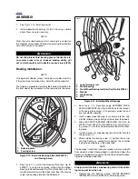
See
Figure 2-24.
When installing rear wheel bearings it
is necessary to use the FORCING SCREW (1) from the
STEERING HEAD BEARING RACE INSTALLER (Part
No. HD-39302).
●
The procedure for the rear wheel bearing installation is
the same as front wheel bearing installation. See
Bear-
ing Installation
in
2.5 FRONT WHEEL
.
●
Install rear wheel bearings using REAR BEARING
INSTALLER (Part No. B-43993-10) and WHEEL BEAR-
ING REMOVER AND INSTALLER (Part No. B-43993-12)
and FORCING SCREW (Part No. HD-39302-2).
1.
Install wheel bearing (3) on rotor side of motorcycle.
2.
Install rear wheel spacer (4).
3.
Install wheel bearing (3) on sprocket side of motorcycle.
4.
Install sprocket.
a. Position sprocket (6) on wheel (5) keeping lip of
sprocket facing the inside.
b.
Install new sprocket fasteners (7) and washers tight-
ening to 35-37 ft-lbs (48-50 Nm).
5.
Install rear rotor (2).
a.
Position rear brake rotor (2) on wheel (5).
b.
Install brake rotor (2) with new rotor mounting fas-
teners (1) and tighten to 25-27 ft-lbs (34-37 Nm).
INSTALLATION
1.
Center rear wheel in the swingarm at the same time slid-
ing the drive belt onto the rear sprocket.
2.
With wheel centered in swingarm, lower bike to align
swingarm and wheel hub.
3.
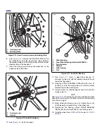
Apply ANTI-SEIZE LUBRICANT to hole in right side of
swingarm where rear axle slides through.
4.
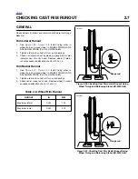
See
Figure 2-25.
Coat the axle with ANTI-SEIZE LUBRI-
CANT.
5.
Slide axle through right side of swing arm and wheel hub
and thread partially into swingarm on left side.
6.
Install idler pulley. See
DRIVE BELT INSTALLATION
in
section
6.6 DRIVE BELT SYSTEM
.
1
CAUTION
Never tighten rear axle with swingarm brace removed.
7.
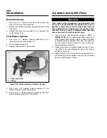
See
Figure 2-26.
Tighten rear axle (1) to 23-27 ft-lbs
(31.2-36.6 Nm), back off two full turns and then retighten
to 48-52 ft-lbs (65.1-70.5 Nm).
8.
Tighten pinch fastener (2) on right side of swingarm to
40-45 ft-lbs (54-61 Nm).
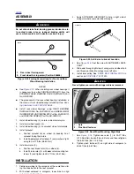
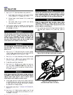
Figure 2-24. Forcing Screws Used for Front and Rear
Wheel Bearing Installation
10096
1.
Rear wheel forcing screw
2.
Front wheel forcing screw (Part No. 280856)
1
2
Figure 2-25. Anti-Seize Lubricant Location
Figure 2-26. Rear Wheel Mounting, Right Side
b1036x2x
8420
2
1.
Axle
2.
Pinch bolt fastener
1
Summary of Contents for 2004 XB9S
Page 2: ......
Page 35: ...D 2 2004 Buell Lightning Appendix D HOME Rear Brake Systems Top View b1115xbsx ...
Page 36: ...2004 Buell Lightning Appendix D D 3 HOME Rear Brake Systems Left Side View b1116xcsx ...
Page 44: ...2004 Buell Lightning Appendix D D 11 HOME Clutch Cable Right Side View b1124xasx ...
Page 47: ...HOME NOTES ...
Page 49: ......
Page 103: ......
Page 201: ...HOME NOTES ...
Page 203: ......
Page 275: ...HOME NOTES ...
Page 307: ...HOME NOTES ...
Page 311: ...HOME NOTES ...
Page 351: ...HOME NOTES ...
Page 441: ......
Page 463: ...HOME NOTES ...
Page 465: ......
Page 517: ...HOME NOTES ...
Page 519: ......
Page 595: ...HOME NOTES ...
Page 597: ......


