


6-6
2004 Buell Lightning: Drive/Transmission
HOME
INSTALLATION
1.
Remove foreign material from magnetic drain plug. Apply
LOCTITE 565 thread sealant and install plug and tighten
to 14-21 ft-lbs (19-28.5 Nm).
2.
Wipe gasket surface clean. Install
new
gasket on pri-
mary cover.
3.
Install primary cover and gasket onto left crankcase half
using mounting bolts.
4.
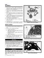
See
Figure 6-3.
Tighten fasteners to 80-110
in-lbs
(9-
12.4 Nm) in sequence shown.
5.
See
Figure 6-1.
Install
new
shifter lever oil seal.
6.
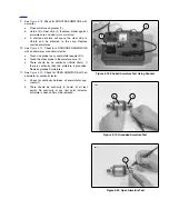
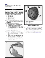
See
Figure 6-4.
Fit coupling (2) over cable end (1) with
rounded side inboard and the ramp connector button out-
board. With retaining ring side of ramp assembly facing
inward, place hook of ramp (3) around coupling button
and rotate assembly counterclockwise until tang on inner
ramp fits in slot of primary cover.
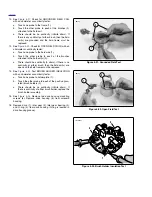
7.
Thread nut on adjustment screw until slot of screw is
accessible with a screwdriver. Fit nut hex into recess of
outer ramp and turn adjustment screw counterclockwise.
8.
Adjust clutch. See
ADJUSTMENT
under
1.9 CLUTCH.
9.
Adjust primary chain tension. See
1.11 PRIMARY
CHAIN
.
10. Fill transmission to proper level with fresh lubricant. See
1.9 CLUTCH
.
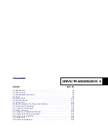
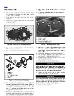
11. See
Figure 6-5.
Install clutch inspection cover (4) with
new
gasket and three TORX screws with washers.
Tighten screws in a crosswise pattern to 84-108
in-lbs
(9.5-12.2 Nm).
12. Install rubber washer and shifter lever assembly (2).
13. After applying LOCTITE 272 (red), tighten engine lever
pinch screw (3) to 48-60
in-lbs
(5.4-6.8 Nm).
14. Install left footpeg support bracket. See
2.30 FOOTPEG,
HEEL GUARD AND MOUNT
.
15. Install chin fairing. See
2.34 CHIN FAIRING
.
1
1
WARNING
1
WARNING
Always connect positive battery cable first. If the positive
cable should contact ground with the negative cable
installed, the resulting sparks may cause a battery explo-
sion which could result in death or serious injury.
16. Connect negative battery cable to battery terminal.
Tighten fastener to 72-96
in-lbs
(8-11 Nm)
1
1
WARNING
1
WARNING
Pull up on seat to verify that it is properly secured, front
and rear. A loose seat may shift during vehicle operation
and startle the rider, possibly causing loss of vehicle
control resulting in death or serious injury.
17. Install seat. See
2.41 SEAT
.
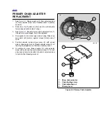
Figure 6-3. Primary Cover Tightening Sequence
Figure 6-4. Clutch Release Mechanism
8801
6
1
7
8
9
11
10
2
12
3
13
4
5
3
2
1
b1055x6x
1.
Cable end
2.
Coupling
3.
Outer ramp and hook
4.
Lockplate
5.
Spring
5
4
Figure 6-5. Installing Primary Cover
1.
Primary cover
2.
Lever, engine
3.
Engine lever pinch screw
4.
Clutch inspection cover
4
1
3
2
8806
Summary of Contents for 2004 XB9S
Page 2: ......
Page 35: ...D 2 2004 Buell Lightning Appendix D HOME Rear Brake Systems Top View b1115xbsx ...
Page 36: ...2004 Buell Lightning Appendix D D 3 HOME Rear Brake Systems Left Side View b1116xcsx ...
Page 44: ...2004 Buell Lightning Appendix D D 11 HOME Clutch Cable Right Side View b1124xasx ...
Page 47: ...HOME NOTES ...
Page 49: ......
Page 103: ......
Page 201: ...HOME NOTES ...
Page 203: ......
Page 275: ...HOME NOTES ...
Page 307: ...HOME NOTES ...
Page 311: ...HOME NOTES ...
Page 351: ...HOME NOTES ...
Page 441: ......
Page 463: ...HOME NOTES ...
Page 465: ......
Page 517: ...HOME NOTES ...
Page 519: ......
Page 595: ...HOME NOTES ...
Page 597: ......