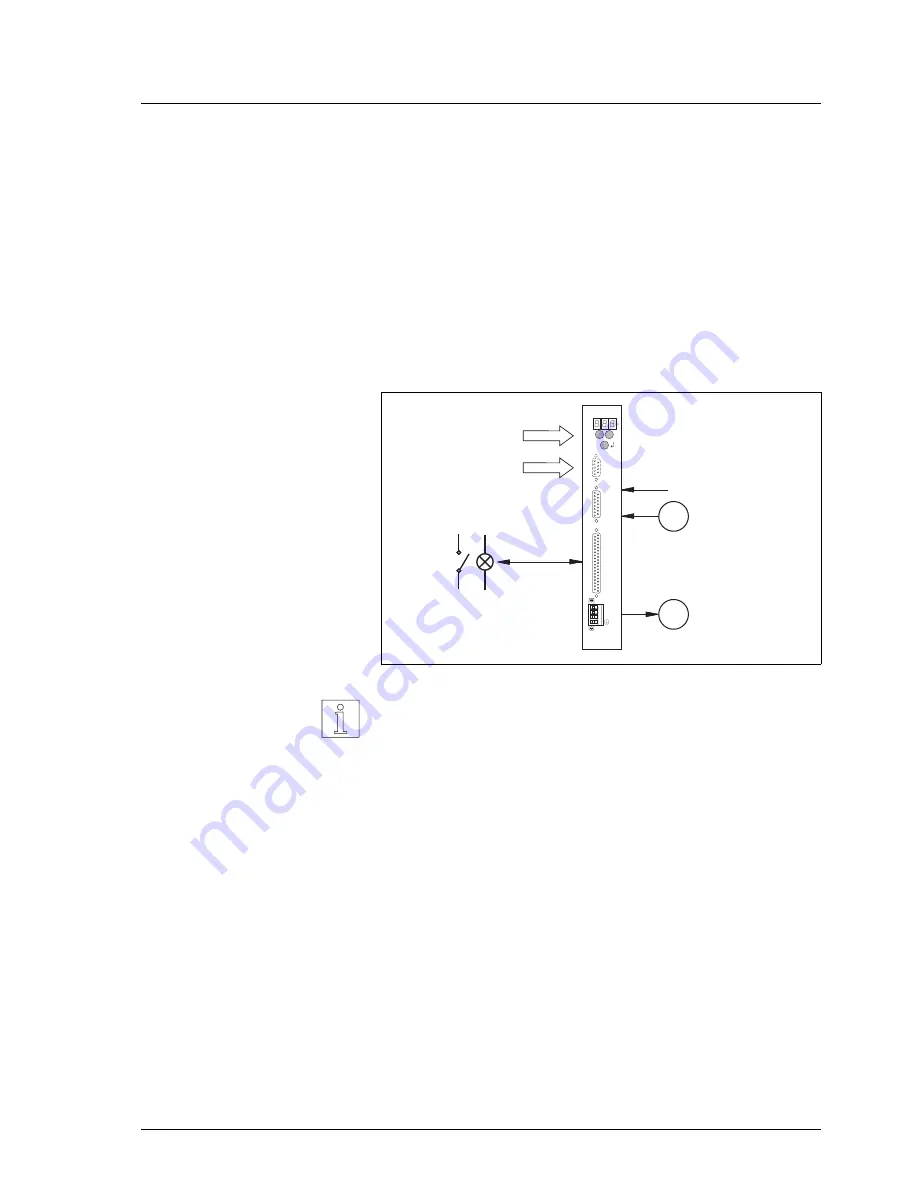
If an RS 422 interface (OPT.2) is installed in the controller, an electronic
gear can be implemented. For this purpose, the parameter P00 = 3 must
be set on the front panel.
In electronic gear mode (fig. 1-7), an external signal and a gear ratio
combine to determine the shaft movement.
Electronic gear
The externally supplied pulses are counted as A/B encoder signals or
pulse/direction signals and multiplied with a gear ratio (parameters P51
and P52). These pulses are used as the reference variable for the
stepping motor position.
The pulse memory is cleared whenever an error occurs or when resetting
input AUTOM from 1 to 0.
The maximum acceleration, the gear ratios and the encoder signal type
are set via front panel parameters.
NOTE
If the controller features a field bus or serial interface in addition, the
electronic gear parameters can be set using on-line command proces-
sing.
M
3-phase
stepping
motor
Pulse, direction
or
encoder
Reference variable:
Signal
inputs/outputs
20
_
+
21
OPT.1
22
OPT.2
23
Signal/
24 V DC
24
V
W
U
L
N
E
Gear
parameters
Fig. 1-7 Operation with
electronic gear
General description
WDP3-01X Ident. no.: 00441109760
1-9


