JetWave 3220v3/3420v3 Series User Manual
Page 10
2.2
Power Installation
The system provides both DC power input and PoE power input.
DC Input
1.
There is one 4-pin terminal block within the package for screwing the DC wires. It is a good
practice to turn off the system power, and to unplug power terminal block before making
wire connections.
2.
Insert the positive and negative wires into the V+ and V- contact on the terminal block
connector. Tighten the wire-clamp screws to prevent DC wires from being loosened. The
range of the suitable electric wire is from 12 to 24 AWG.
3.
The typical and suggest power source is DC 24V, the acceptable range is range from
12~48V. Please note that while you connect 48VDC, make sure the inrush voltage shall be
under 10% (52.8V).
4.
The dual DC power can be redundant. You can connect one power to typical power source
and the other to battery/UPS as backup. However, the DC power input can’t redundant with
PoE. Please see the note at 2.2.3.
Powered by PoE
1.
Connect the Ethernet cable to the Ethernet Port
1 in the front of the JetWave 3200 Series. The
Ethernet port 1 is an IEEE 802.3at compliant
PoE port.
2.
If you are connecting the JetWave 3200 Series,
the PoE function is applied to the Radio
interface and the Eth 1. Eth 2 is only applied for
data transmission.
3.
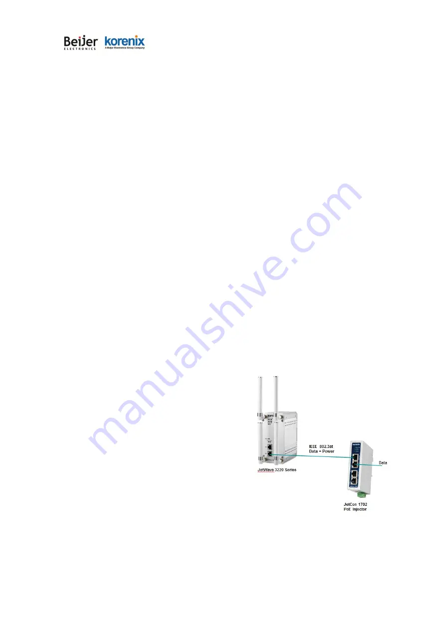
While selecting power source by PoE, connect
another end of the Ethernet cable to the PoE Switch or PoE Injector. Then the AP can be
powered and user can access its management interface through the cable. The figure in right
is an example of Connect AP to the PoE injector.
Note 1:
Please choose Korenix Industrial IEEE 802.3at compliant PoE Injector or Switch as the
Summary of Contents for korenix JetWave 3220v3 Series
Page 10: ...JetWave 3220v3 3420v3 Series User Manual Page 1 Chapter 1 Introduction...
Page 14: ...JetWave 3220v3 3420v3 Series User Manual Page 5 JetWave 3420v3 Appearance...
Page 17: ...JetWave 3220v3 3420v3 Series User Manual Page 8 Chapter 2 Hardware Installation...
Page 34: ...JetWave 3220v3 3420v3 Series User Manual Page 25 Celling mounting Plate Dimension...
Page 42: ...JetWave 3220v3 3420v3 Series User Manual Page 33 Chapter 3 Prepare for Management...
Page 50: ...JetWave 3220v3 3420v3 Series User Manual Page 41 Chapter 4 Web GUI Configuration...
Page 52: ...JetWave 3220v3 3420v3 Series User Manual Page 43...
Page 120: ...JetWave 3220v3 3420v3 Series User Manual Page 111 Example wlanSetting wlanSettingEntry...
Page 132: ...JetWave 3220v3 3420v3 Series User Manual Page 123 Chapter 6 Troubleshooting...


