


ADR241B
Doc ID : ADR241B-DO_IM_01
Ref ID : ADR241B/IM/PC-SI
Rev No.
: 06
Page No. : 66 of 272
3.5.2
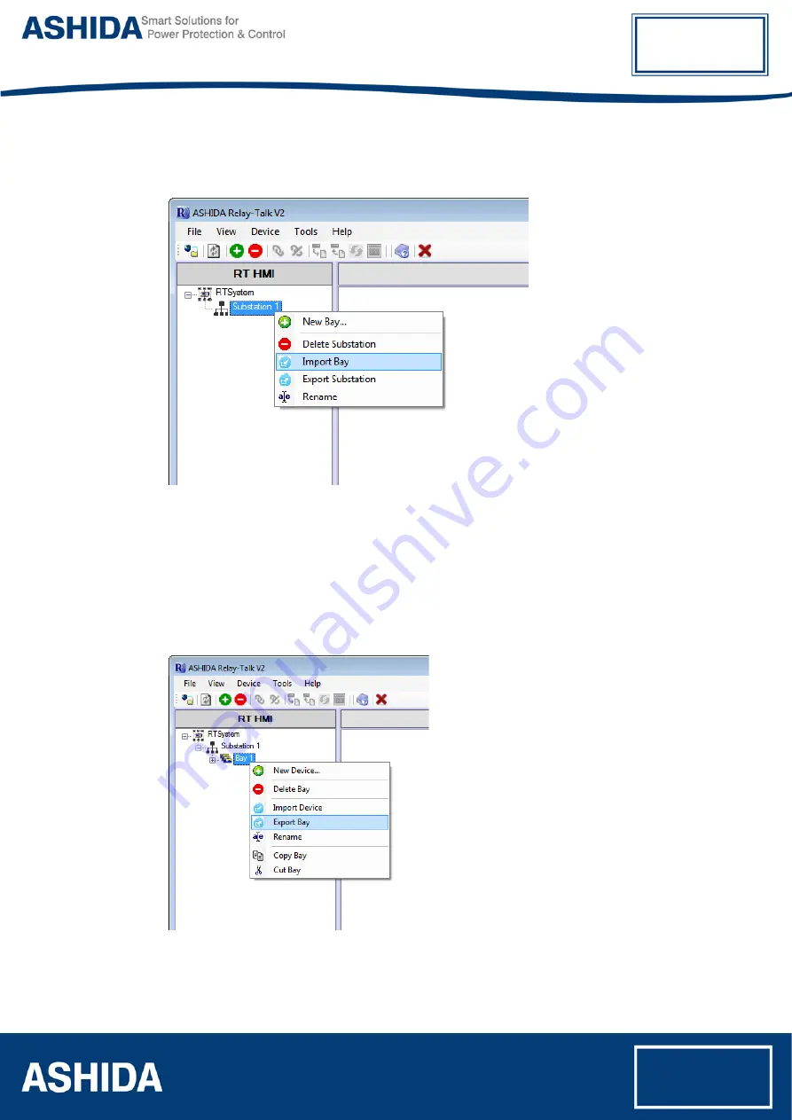
Import Bay
To import bay right click on substation. Following context menu will appear.
Figure 18: Import Bay
Now click on “Import Bay” .In the “Import Bay” dialogue select a system archive to import and
click Open.
3.5.3
Export Bay
To export bay right click on Bay. Following context menu will appear.
Figure 19: Export Bay
Now click on “Export Bay” following window will appear.
Summary of Contents for ADR241B
Page 10: ...Page intentionally Left Blank...
Page 20: ...Page intentionally Left Blank...
Page 34: ...Page intentionally Left Blank...
Page 50: ...Page intentionally Left Blank...
Page 87: ...Page intentionally Left Blank...
Page 111: ...Page intentionally Left Blank...
Page 115: ...Page intentionally Left Blank...
Page 129: ...Page intentionally Left Blank...
Page 145: ...Page intentionally Left Blank...
Page 217: ...Page intentionally Left Blank...
Page 255: ...Page intentionally Left Blank...
Page 261: ...ADR241B Doc ID ADR241B DO_IM_01 Ref ID ADR241B IM DR Rev No 06 Page No 261 of 272 Event Record...
Page 262: ...Page intentionally Left Blank...