6.10 Setting the Auto Survey Mode
53
6.10
Setting the Auto Survey Mode
Use one of the Auto Survey modes to control how and when the clock determines position infor-
mation. The accuracy of the position (and indirectly, time) is based on averaging the assigned
number of position fixes surveyed, either during startup or by a single survey. At the conclusion
of a survey, the clock is placed in Position Hold mode and the averaged position is placed into
memory. If accurate position information is used, this results in a reduced standard deviation for
the time data.
RS-232C: see Section 9.2.8
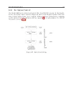
There are five Auto Survey modes available:
1. Turn Off Survey – halt the survey in progress
2. Single Survey – initiate a new survey at this time
3. Power-On Survey – initiate a new survey when the clock is powered on
4. Suspend Survey – pause a survey in progress
5. Resume Survey – resume a survey that was paused
Figure 6.20: Survey Mode Setup
6.10.1
Number of Fixes
Auto Survey configuration presents a list of possible surveys from 1 to 86,400 seconds (approx. 24
hours). Surveys are listed as 1 (single fix), 60 (1 minute or more), 300 (5 minutes or more), 900 (15
minutes or more), 1800 (30 minutes or more), 3600 (1 hour or more), 7200 (2 hours or more), 14400
(4 hours or more), 28800 (8 hours or more), 43200 (12 hours or more), and 86400 (24 hours or
more). To complete a survey, the GPS receiver must be tracking at least four satellites. If, during
a survey, the number of satellites being tracked drops below four, the survey will pause until the
GPS receiver again begins tracking four or more satellites. Then, the survey will resume computing
positions until completion.
Summary of Contents for 1088A
Page 4: ...iv ...
Page 6: ...vi ...
Page 18: ...xviii LIST OF FIGURES ...
Page 23: ...1 4 Attaching Rack Mount Ears to 1088A B Series Clocks 3 Figure 1 2 Attaching Rack Mount Ears ...
Page 24: ...4 Unpacking the Clock ...
Page 32: ...12 Front and Rear Panels ...
Page 38: ...18 Connecting Inlet Power Input and Output Signals ...
Page 46: ...26 GPS Antenna and Cable Information ...
Page 48: ...28 Setting Internal Jumpers Figure 5 1 Model 1088B Main Board ...
Page 76: ...56 The Setup Menus ...
Page 112: ...92 Serial Communication and Command Set ...
Page 127: ...B 4 Physical Dimensions 107 Figure B 1 Suggested Mounting of the AS0094500 Surge Arrester ...
Page 128: ...108 Using Surge Arresters ...
Page 145: ...C 5 Option 04 Parallel BCD Output 125 Figure C 4 Option 04 Output Jumper Settings ...
Page 146: ...126 Options List Figure C 5 Option 04 Board Layout and Jumper Locations ...
Page 166: ...146 Options List Figure C 12 Option 17 Board Layout and Jumper Locations ...
Page 187: ...C 16 Option 20A Four Fiber Optic Outputs 167 Figure C 22 Option 20A Jumper Locations ...
Page 194: ...174 Options List Figure C 24 Option 23 Internal Jumper Setup ...
Page 196: ...176 Options List Figure C 25 Option 27 Jumper Locations ...
Page 214: ...194 Options List Figure C 28 Option 29 Connector Signal Locations ...
Page 270: ...250 Options List ...


