C.23 Option 36: Four Configurable Outputs
247
General Information
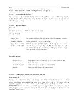
Option 36 incorporates a flexible output selection system using jumpers on the Option 36 printed
circuit board. Each of the four rear-panel BNC-type I/O connectors, included with Option 36, can
be configured to perform any of the available output functions. Figure C.61 shows the locations
and Table C.18 indicates the functions for all of the jumpers on the Option 36 board.
Function Selection
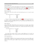
Jumpers JMP1, JMP2, JMP3 and JMP4 control which output signal arrives at a respective output
connector.
Desired Output Connector
Function Jumper
J2
JMP1
J3
JMP2
J4
JMP3
J5
JMP4
Compare each jumper position with the items in Table C.18 to match your desired signal type.
For example, to provide unmodulated IRIG-B at output connector J2, set JMP1 jumper pin to
position 3. If all of the four outputs need to be set to provide unmodulated IRIG-B, place each
function jumper to position 3.
Mode Selection
Jumpers JMP9, JMP10, JMP11, JMP12 control the signal driver for each output: analog or digital.
Make sure to select these output mode jumpers for each output. For each output, position A selects
a digital driver and position B selects an analog driver. The table below indicates the correct jumper
for each output.
Desired Output Connector
Mode Jumper
J2
JMP9
J3
JMP10
J4
JMP11
J5
JMP12
On the 1088A/B two signals are defined as analog: modulated IRIG-B and
±
5 V deviation. On
all Mode jumpers, JMP9 – JMP12, analog signals use position B. Digital signals, like unmodulated
IRIG-B, use position A.
Clock Model Selection
Jumpers JMP13 and JMP14 select the clock model in which Option 36 is mounted. JMP13 selects
for Model 1088B and JMP14 selects for Model 1084A/B/C, Model 1093A/B/C and Model 1201B/C.
Make sure to to set this jumper to JMP13 or Option 36 will not operate correctly in the Model
1088A/B.
Summary of Contents for 1088A
Page 4: ...iv ...
Page 6: ...vi ...
Page 18: ...xviii LIST OF FIGURES ...
Page 23: ...1 4 Attaching Rack Mount Ears to 1088A B Series Clocks 3 Figure 1 2 Attaching Rack Mount Ears ...
Page 24: ...4 Unpacking the Clock ...
Page 32: ...12 Front and Rear Panels ...
Page 38: ...18 Connecting Inlet Power Input and Output Signals ...
Page 46: ...26 GPS Antenna and Cable Information ...
Page 48: ...28 Setting Internal Jumpers Figure 5 1 Model 1088B Main Board ...
Page 76: ...56 The Setup Menus ...
Page 112: ...92 Serial Communication and Command Set ...
Page 127: ...B 4 Physical Dimensions 107 Figure B 1 Suggested Mounting of the AS0094500 Surge Arrester ...
Page 128: ...108 Using Surge Arresters ...
Page 145: ...C 5 Option 04 Parallel BCD Output 125 Figure C 4 Option 04 Output Jumper Settings ...
Page 146: ...126 Options List Figure C 5 Option 04 Board Layout and Jumper Locations ...
Page 166: ...146 Options List Figure C 12 Option 17 Board Layout and Jumper Locations ...
Page 187: ...C 16 Option 20A Four Fiber Optic Outputs 167 Figure C 22 Option 20A Jumper Locations ...
Page 194: ...174 Options List Figure C 24 Option 23 Internal Jumper Setup ...
Page 196: ...176 Options List Figure C 25 Option 27 Jumper Locations ...
Page 214: ...194 Options List Figure C 28 Option 29 Connector Signal Locations ...
Page 270: ...250 Options List ...


