14
Connecting Inlet Power, Input and Output Signals
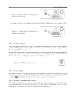
Figure 3.1: IEC-320 Power Supply Inlet De-
scription
3.2.1
Cordsets and Plug Styles for IEC-320 Inlet Module
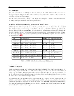
Make sure that the cordset matches the wall connector for your country. The following are available
IEC-320 mating cordset plug style and specifications:
No.
Country
Specification
Rating
P01
Continental Europe
CEE 7/7
220V
P02
Australia, NZ, PRC
AS3112-1981
240V
P03
U.K.
BS 1363
240V
P04
Denmark
Afsnit 107-2-01
240V
P05
India
BS 546
220V
P06
Israel
SI 32
220V
P07
Italy
CEI 23-16/VII 1971
220V
P08
Switzerland
SEV 1011.1959
220V
P09
North America and ROC
NEMA 5-15P CSA C22.2#42
120V
P10
Japan
JIS8303
120V
Table 3.1: Available IEC-320 Cordsets by Country
3.2.2
IEC-320, Connecting Power to the 1088B
Connect the IEC-320 plug to the IEC-320 connector on the 1088B, and then connect the wall plug
into the wall socket.
3.3
Option 07, 110 to 370 Vdc Terminal Power Strip
This option replaces the standard IEC-320 inlet with a 3-pole terminal strip. Input voltages are:
85 to 264 Vac, 47 to 440 Hz, or 110 to 370 Vdc,
<
20 VA typical.
3.3.1
Option 07, Connecting Inlet Power
When wiring this power supply, make sure to first connect an earth ground wire to the terminal strip
connector labeled ”G” (for ground). Positive and negative terminals are marked on the terminals
Summary of Contents for 1088A
Page 4: ...iv ...
Page 6: ...vi ...
Page 18: ...xviii LIST OF FIGURES ...
Page 23: ...1 4 Attaching Rack Mount Ears to 1088A B Series Clocks 3 Figure 1 2 Attaching Rack Mount Ears ...
Page 24: ...4 Unpacking the Clock ...
Page 32: ...12 Front and Rear Panels ...
Page 38: ...18 Connecting Inlet Power Input and Output Signals ...
Page 46: ...26 GPS Antenna and Cable Information ...
Page 48: ...28 Setting Internal Jumpers Figure 5 1 Model 1088B Main Board ...
Page 76: ...56 The Setup Menus ...
Page 112: ...92 Serial Communication and Command Set ...
Page 127: ...B 4 Physical Dimensions 107 Figure B 1 Suggested Mounting of the AS0094500 Surge Arrester ...
Page 128: ...108 Using Surge Arresters ...
Page 145: ...C 5 Option 04 Parallel BCD Output 125 Figure C 4 Option 04 Output Jumper Settings ...
Page 146: ...126 Options List Figure C 5 Option 04 Board Layout and Jumper Locations ...
Page 166: ...146 Options List Figure C 12 Option 17 Board Layout and Jumper Locations ...
Page 187: ...C 16 Option 20A Four Fiber Optic Outputs 167 Figure C 22 Option 20A Jumper Locations ...
Page 194: ...174 Options List Figure C 24 Option 23 Internal Jumper Setup ...
Page 196: ...176 Options List Figure C 25 Option 27 Jumper Locations ...
Page 214: ...194 Options List Figure C 28 Option 29 Connector Signal Locations ...
Page 270: ...250 Options List ...


