9.2 Command Set
77
9.2.3
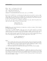
Status Mode Commands
Return Status of Event/Deviation
Command:
SA, SB
SA and SB return the event/deviation channel setup information for channels A and B respectively,
read index number and write index number.
Response:
D(E), R = nnn, S = mmm
C
Format:
D
indicates the input channel is in 1–PPS deviation mode
E
indicates the input channel is in event mode
nnn
= Channel read index (000 to 199)
mmm = Channel write index (000 to 199)
NOTE: When nnn = mmm, using the EA or EB command to read event data, the event buffer is
empty, i.e., all event data which has been recorded has also been read.
Return Clock Status
Command:
SC
SC returns the current clock status.
Response:
L/U, U=xx, S=nn
C
Format:
L
= Clock currently locked to GPS (U for unlocked).
xx
= Indicates loss of lock period, up to 99 minutes.
nn
= User specified out-of-lock delay, 00 to 99 minutes (refer to Table A-8).
S
= Off if the out-of-lock function is deactivated, S = ZDL indicates zero delay.
Receiver Status
Command:
SR
SR returns the current receiver status.
Response:
V=vv S=ss T=t P=Off E=0
C
Format:
vv
= number of satellites, visible to the antenna, per almanac.
ss
= relative signal strength (range: 0 to 255, nominal value = 15)
t
= number of satellites being actively tracked (up to twelve)
P
= Off, indicates that the time dilution of precision (TDOP)
calculation is not being performed. Returns 1.0 99.0, depending
on satellite geometry, when TDOP calculation is being performed.
A TDOP calculation is NOT performed if less than 3 satellites are
visible, OR if Position-Hold is active. E = 0, currently unused.
Summary of Contents for 1088A
Page 4: ...iv ...
Page 6: ...vi ...
Page 18: ...xviii LIST OF FIGURES ...
Page 23: ...1 4 Attaching Rack Mount Ears to 1088A B Series Clocks 3 Figure 1 2 Attaching Rack Mount Ears ...
Page 24: ...4 Unpacking the Clock ...
Page 32: ...12 Front and Rear Panels ...
Page 38: ...18 Connecting Inlet Power Input and Output Signals ...
Page 46: ...26 GPS Antenna and Cable Information ...
Page 48: ...28 Setting Internal Jumpers Figure 5 1 Model 1088B Main Board ...
Page 76: ...56 The Setup Menus ...
Page 112: ...92 Serial Communication and Command Set ...
Page 127: ...B 4 Physical Dimensions 107 Figure B 1 Suggested Mounting of the AS0094500 Surge Arrester ...
Page 128: ...108 Using Surge Arresters ...
Page 145: ...C 5 Option 04 Parallel BCD Output 125 Figure C 4 Option 04 Output Jumper Settings ...
Page 146: ...126 Options List Figure C 5 Option 04 Board Layout and Jumper Locations ...
Page 166: ...146 Options List Figure C 12 Option 17 Board Layout and Jumper Locations ...
Page 187: ...C 16 Option 20A Four Fiber Optic Outputs 167 Figure C 22 Option 20A Jumper Locations ...
Page 194: ...174 Options List Figure C 24 Option 23 Internal Jumper Setup ...
Page 196: ...176 Options List Figure C 25 Option 27 Jumper Locations ...
Page 214: ...194 Options List Figure C 28 Option 29 Connector Signal Locations ...
Page 270: ...250 Options List ...


