204
Options List
PC Port Pins
Clock Port Pins
Port Function
2
3
Transmit
3
2
Receive
5
5
Ground
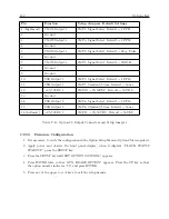
Table C.15: Null-Modem Cable Connections
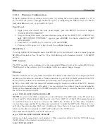
3. For Model 1088A/B type “1,11,1088XI” (without quotes) and the cursor should jump down
to the next line without displaying a question mark.
4. Option 34 should now be selected in your clock.
5. To test it, type “IP” and it should return the IP addresses of the two Ethernet ports. With
no Ethernet cable connected to a port, the IP command will return dashes for the IP address
of that port. The MAC address will still be returned as illustrated below.
NET1:192.168.000.232 64:73:E2:XX:XX:XX
(Static IP)
NET2:---.---.---.--- 64:73:E2:XX:XX:XX
(DHCP)
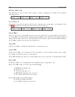
Logging in with the Web Interface
See Section C.22.3 for details on using the web interface.
NTP Status Display Indications
During the stabilization process, the clock will display different status messages that indicate
whether the NTP server is ready to serve time. Clock stabilization requires the clock to be locked
to the GPS for a period of time after which it will provide its time to the Option 34. To view
NTP/PTP status messages, press the SYSTEM key several times until reaching
OPTION STATUS
,
then press
ENTER
and the UP or DOWN key.
Server Status: Waiting for clock to lock to satellites.
NTP: PLEASE WAIT
PTP: PLEASE WAIT
Server Status: Waiting for NTP to stabilize (up to 1 hour).
NTP: UNLOCKED
PTP: RUNNING
Server Status: Normal Operation.
NTP: LOCKED
PTP: RUNNING
Server Status: Synchronization problem on the Option 34 – clock may not be locked.
NTP: ERROR
PTP: RUNNING
Summary of Contents for 1088A
Page 4: ...iv ...
Page 6: ...vi ...
Page 18: ...xviii LIST OF FIGURES ...
Page 23: ...1 4 Attaching Rack Mount Ears to 1088A B Series Clocks 3 Figure 1 2 Attaching Rack Mount Ears ...
Page 24: ...4 Unpacking the Clock ...
Page 32: ...12 Front and Rear Panels ...
Page 38: ...18 Connecting Inlet Power Input and Output Signals ...
Page 46: ...26 GPS Antenna and Cable Information ...
Page 48: ...28 Setting Internal Jumpers Figure 5 1 Model 1088B Main Board ...
Page 76: ...56 The Setup Menus ...
Page 112: ...92 Serial Communication and Command Set ...
Page 127: ...B 4 Physical Dimensions 107 Figure B 1 Suggested Mounting of the AS0094500 Surge Arrester ...
Page 128: ...108 Using Surge Arresters ...
Page 145: ...C 5 Option 04 Parallel BCD Output 125 Figure C 4 Option 04 Output Jumper Settings ...
Page 146: ...126 Options List Figure C 5 Option 04 Board Layout and Jumper Locations ...
Page 166: ...146 Options List Figure C 12 Option 17 Board Layout and Jumper Locations ...
Page 187: ...C 16 Option 20A Four Fiber Optic Outputs 167 Figure C 22 Option 20A Jumper Locations ...
Page 194: ...174 Options List Figure C 24 Option 23 Internal Jumper Setup ...
Page 196: ...176 Options List Figure C 25 Option 27 Jumper Locations ...
Page 214: ...194 Options List Figure C 28 Option 29 Connector Signal Locations ...
Page 270: ...250 Options List ...


