C.18 Option 27: 8-Channel High Drive
175
C.18
Option 27: 8-Channel High Drive
C.18.1
General Description
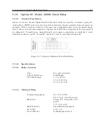
Option 27 provides eight independent, IRIG-B buffered outputs, each capable of driving multiple
loads. Outputs are short circuit and surge protected. Each output is individually configurable for
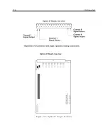
either modulated or unmodulated IRIG-B signals via jumper settings as illustrated in Figure C.25.
C.18.2
Specifications
Output Selection
Each output is jumper selectable for either a Modulated or Unmodulated signal.
See Figure C.25 for jumper locations and configuration settings.
Number of Channels:
Eight (8).
Signal Levels:
Modulated:
4.5 Vpp with 20-Ohm source impedance; each channel
will drive a 50-Ohm load to 3 Vpp minimum;
Unmodulated:
+5-V open-circuit; +4 V minimum at 250-mA load
load current each channel will drive 25 Schweitzer
SEL-3xx (in parallel) or 50 SEL-2xx (in series/parallel)
relays at 10 mA per relay.
Maximum Load (per driver):
Modulated:
No Limit: will drive a short circuit.
Unmodulated:
250-mA peak current; pulse-by-pulse shutdown if load
current exceeds internal limit (self-resetting).
Output Connector
16-position pluggable 5-mm (Phoenix-type) terminal strip with eight 2-position mating connectors.
C.18.3
Option Setup
Using Front Panel Keys
To set up Option 27 from the front-panel keys, please follow the guidelines in Section 6.12.
Using RS-232C Port
To set up Option 27 using the RS-232C port, please follow the guidelines in Section 9.2.13.
Summary of Contents for 1088A
Page 4: ...iv ...
Page 6: ...vi ...
Page 18: ...xviii LIST OF FIGURES ...
Page 23: ...1 4 Attaching Rack Mount Ears to 1088A B Series Clocks 3 Figure 1 2 Attaching Rack Mount Ears ...
Page 24: ...4 Unpacking the Clock ...
Page 32: ...12 Front and Rear Panels ...
Page 38: ...18 Connecting Inlet Power Input and Output Signals ...
Page 46: ...26 GPS Antenna and Cable Information ...
Page 48: ...28 Setting Internal Jumpers Figure 5 1 Model 1088B Main Board ...
Page 76: ...56 The Setup Menus ...
Page 112: ...92 Serial Communication and Command Set ...
Page 127: ...B 4 Physical Dimensions 107 Figure B 1 Suggested Mounting of the AS0094500 Surge Arrester ...
Page 128: ...108 Using Surge Arresters ...
Page 145: ...C 5 Option 04 Parallel BCD Output 125 Figure C 4 Option 04 Output Jumper Settings ...
Page 146: ...126 Options List Figure C 5 Option 04 Board Layout and Jumper Locations ...
Page 166: ...146 Options List Figure C 12 Option 17 Board Layout and Jumper Locations ...
Page 187: ...C 16 Option 20A Four Fiber Optic Outputs 167 Figure C 22 Option 20A Jumper Locations ...
Page 194: ...174 Options List Figure C 24 Option 23 Internal Jumper Setup ...
Page 196: ...176 Options List Figure C 25 Option 27 Jumper Locations ...
Page 214: ...194 Options List Figure C 28 Option 29 Connector Signal Locations ...
Page 270: ...250 Options List ...

