152
Options List
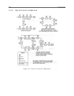
Redundant Clock Control
Interface
Interconnect:
Using Arbiter Systems P/N CA0017200 cable assembly.
Communications:
Uses RS-232 port and two dedicated hardware lines.
Relays
Two, form-C (SPDT), fail-safe (in faulted position with
power off).
Contact Rating:
130 Vdc at 0.3 A; 24 Vdc at 1 A.
Function:
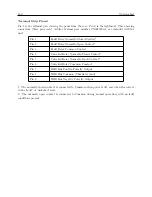
Unlocked (energized when locked to satellites);Fault (ener-
gized when no fault conditions present).
Associated Products
Model 10882A
IRIG-B Distribution Tap
Model 10883A
IRIG-B Distribution Bus Splitter
Model 10884A
IRIG-B Distribution Bus Terminator
Model 10885A
IRIG-B Distribution Redundant Ring Adapter
C.14.3
Discussion – IRIG-B Distribution System
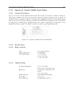
Option 18 for the Model 1088B GPS Satellite-Controlled Clock provides an IRIG-B distribution
bus output which is capable of driving 24 separate taps, loaded at 600 ohms, over a length of 500
meters of cable. Longer cable lengths, or more taps, may be possible, depending on the loading
and signal levels required.
Option 18 includes a built-in distribution system monitor, which continually checks for two condi-
tions: the presence of an IRIG signal at the bus output terminals, and dc electrical continuity in the
distribution bus cable. Any fault in the clock mainframe or Option 18 board which results in loss
of IRIG drive, any bus short within approximately one kilometer of the clock (or more, depending
on bus configuration and loading), and any electrical open circuit (a cut cable, for instance) will
be detected and reported as a FAULT via the front-panel FAULT LED, the FAULT relay output,
and RS-232.
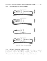
Even in the presence of a break in the cable, service may be maintained at all taps, and the break
detected and reported for maintenance, using the Model 10885A IRIG-B Distribution Redundant-
Ring Adapter with a ring or loop-configured distribution bus (where the ’far end’ of the bus is
physically brought back to the start). This allows the system to offer a substantial degree of
survivability with respect to broken cables, while nonetheless reporting the problem for corrective
action. The Model 10885A also provides 3750 Vrms isolation from the return end of the bus to the
clock mainframe, to prevent voltages induced in the bus loop from causing currents to flow in the
distribution bus or its shield.
Summary of Contents for 1088A
Page 4: ...iv ...
Page 6: ...vi ...
Page 18: ...xviii LIST OF FIGURES ...
Page 23: ...1 4 Attaching Rack Mount Ears to 1088A B Series Clocks 3 Figure 1 2 Attaching Rack Mount Ears ...
Page 24: ...4 Unpacking the Clock ...
Page 32: ...12 Front and Rear Panels ...
Page 38: ...18 Connecting Inlet Power Input and Output Signals ...
Page 46: ...26 GPS Antenna and Cable Information ...
Page 48: ...28 Setting Internal Jumpers Figure 5 1 Model 1088B Main Board ...
Page 76: ...56 The Setup Menus ...
Page 112: ...92 Serial Communication and Command Set ...
Page 127: ...B 4 Physical Dimensions 107 Figure B 1 Suggested Mounting of the AS0094500 Surge Arrester ...
Page 128: ...108 Using Surge Arresters ...
Page 145: ...C 5 Option 04 Parallel BCD Output 125 Figure C 4 Option 04 Output Jumper Settings ...
Page 146: ...126 Options List Figure C 5 Option 04 Board Layout and Jumper Locations ...
Page 166: ...146 Options List Figure C 12 Option 17 Board Layout and Jumper Locations ...
Page 187: ...C 16 Option 20A Four Fiber Optic Outputs 167 Figure C 22 Option 20A Jumper Locations ...
Page 194: ...174 Options List Figure C 24 Option 23 Internal Jumper Setup ...
Page 196: ...176 Options List Figure C 25 Option 27 Jumper Locations ...
Page 214: ...194 Options List Figure C 28 Option 29 Connector Signal Locations ...
Page 270: ...250 Options List ...


