C.14 Option 18: IRIG-B BUS Distribution, Fault Monitor and 2nd RS-232 Port
151
C.14
Option 18: IRIG-B BUS Distribution, Fault Monitor and
2nd RS-232 Port
C.14.1
General Description
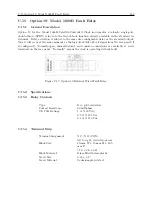
Option 18 for the Model 1088B adds several capabilities to the clock, which are often used in
systems applications. These capabilities include:
•
An IRIG-B distribution bus amplifier that drives dozens of loads over distances of hundreds
of meters
•
A fault monitor that expands the ability of the Model 1088B to detect internal faults and
provides two form-C (SPDT) fail-safe relay contact sets to indicate the Unlocked and Fault
conditions. These relay contacts are for connection to external equipment such as a digital
fault recorder.
•
A second serial (RS-232) port, which can be used as a status event logger, for a broadcast
time output, to connect to a second computer; or as a redundant clock interface allowing two
Model 1088B clocks to be interconnected to form a redundant timing system.
C.14.2
Specifications
IRIG-B Distribution Bus
Output Connector:
Pluggable terminal strip, 5mm centers.
Loads
24, minimum, with Model 10882A load taps.
Bus Length
Limited by bus configuration; will drive 500m (1500’) of
AWG18 twisted-pair cable in a linear configuration.
Delay
Less than 100 microseconds, typical; depends on loading and
bus configuration.
Output Level, Tap Output
6.4-11 Vpp, open-circuit; 3.2-5.5 Vpp, into 600 ohm load.
Fault Monitor
Indication:
Via rear-panel relay, front-panel display, or serial port.
Faults Detected:
IRIG-B Distribution:
Three fault modes will generate an alarm: any break in the
distribution bus; or a short circuit, or load impedance below
50 ohms; or any loss of the IRIG-B drive signal.
Processor:
Watchdog violation or other reset condition.
Power Supply:
5 volt, +12 volt and -12 volt supplies out of limits.
Summary of Contents for 1088A
Page 4: ...iv ...
Page 6: ...vi ...
Page 18: ...xviii LIST OF FIGURES ...
Page 23: ...1 4 Attaching Rack Mount Ears to 1088A B Series Clocks 3 Figure 1 2 Attaching Rack Mount Ears ...
Page 24: ...4 Unpacking the Clock ...
Page 32: ...12 Front and Rear Panels ...
Page 38: ...18 Connecting Inlet Power Input and Output Signals ...
Page 46: ...26 GPS Antenna and Cable Information ...
Page 48: ...28 Setting Internal Jumpers Figure 5 1 Model 1088B Main Board ...
Page 76: ...56 The Setup Menus ...
Page 112: ...92 Serial Communication and Command Set ...
Page 127: ...B 4 Physical Dimensions 107 Figure B 1 Suggested Mounting of the AS0094500 Surge Arrester ...
Page 128: ...108 Using Surge Arresters ...
Page 145: ...C 5 Option 04 Parallel BCD Output 125 Figure C 4 Option 04 Output Jumper Settings ...
Page 146: ...126 Options List Figure C 5 Option 04 Board Layout and Jumper Locations ...
Page 166: ...146 Options List Figure C 12 Option 17 Board Layout and Jumper Locations ...
Page 187: ...C 16 Option 20A Four Fiber Optic Outputs 167 Figure C 22 Option 20A Jumper Locations ...
Page 194: ...174 Options List Figure C 24 Option 23 Internal Jumper Setup ...
Page 196: ...176 Options List Figure C 25 Option 27 Jumper Locations ...
Page 214: ...194 Options List Figure C 28 Option 29 Connector Signal Locations ...
Page 270: ...250 Options List ...


