8
Front and Rear Panels
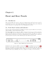
Time
Sets the display to the Time Display Mode. There are four modes of the time display available and
repeated pressing of this key will cause the display to scroll through all four modes. Changing the
time display has no effect on the time data, which is output from rear-panel timing outputs.
Position
Cycles the display through the longitude, latitude, and elevation data readouts of the antenna
location according to the most recent, or averaged, position fix.
Event/Deviation
Selects Event and/or Deviation Data recorded by the specific Model clock; up to 200 event records
for each channel (A and B) or updated 1-PPS deviation data. For additional information, see Event
Inputs in Chapters 5, 6, 8 and 9.
Status
Toggles the display between four status display modes: Clock, Receiver, DXCO and EEPROM,
including the display of GPS satellite acquisition and synchronization.
Setup
Invokes a series of menus used to adjust configurable parameters within the clock. In numeric data
entry mode, moves the cursor to the left.
Up
Used in conjunction with the Setup menus to adjust values upward, or to scroll upward through
the available menu choices. Also assists in navigating through main Setup menus in normal order.
Down
Used in conjunction with the Setup menus to adjust values downward, or to scroll downward
through available menu choices. Also assists in navigating through main Setup menus in reverse.
Enter
Used for confirming changes made within Setup menus. Generally, pressing Enter also advances to
the next parameter, or returns to the previous menu level. In numeric data entry mode, moves the
cursor to the right.
2.3
Rear Panel Identification and Connectors
This section contains information to assist you in identifying where to connect inlet power, the
GPS antenna cable and all of the input and output cables on the Model 1088A/B series clocks.
Figure 2.2: Model 1088A/B Rear Panel Description
Summary of Contents for 1088A
Page 4: ...iv ...
Page 6: ...vi ...
Page 18: ...xviii LIST OF FIGURES ...
Page 23: ...1 4 Attaching Rack Mount Ears to 1088A B Series Clocks 3 Figure 1 2 Attaching Rack Mount Ears ...
Page 24: ...4 Unpacking the Clock ...
Page 32: ...12 Front and Rear Panels ...
Page 38: ...18 Connecting Inlet Power Input and Output Signals ...
Page 46: ...26 GPS Antenna and Cable Information ...
Page 48: ...28 Setting Internal Jumpers Figure 5 1 Model 1088B Main Board ...
Page 76: ...56 The Setup Menus ...
Page 112: ...92 Serial Communication and Command Set ...
Page 127: ...B 4 Physical Dimensions 107 Figure B 1 Suggested Mounting of the AS0094500 Surge Arrester ...
Page 128: ...108 Using Surge Arresters ...
Page 145: ...C 5 Option 04 Parallel BCD Output 125 Figure C 4 Option 04 Output Jumper Settings ...
Page 146: ...126 Options List Figure C 5 Option 04 Board Layout and Jumper Locations ...
Page 166: ...146 Options List Figure C 12 Option 17 Board Layout and Jumper Locations ...
Page 187: ...C 16 Option 20A Four Fiber Optic Outputs 167 Figure C 22 Option 20A Jumper Locations ...
Page 194: ...174 Options List Figure C 24 Option 23 Internal Jumper Setup ...
Page 196: ...176 Options List Figure C 25 Option 27 Jumper Locations ...
Page 214: ...194 Options List Figure C 28 Option 29 Connector Signal Locations ...
Page 270: ...250 Options List ...


