C.18 Option 27: 8-Channel High Drive
177
C.18.4
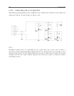
Output Load and Loop Example – Unmodulated IRIG-B
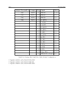
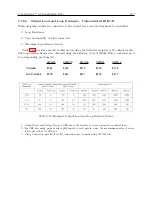
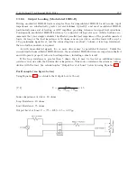
When designing circuits for connection to the output bus, several factors must be considered.
1. Loop Resistance
2. Type and quantity of loads connected
3. Maximum loop distance desired
Table C.10 provides a matrix of these factors using the Schweitzer relay(s) as the output load(s).
The loop distance figures were obtained using the following types of Belden Wire (cross-referenced
to corresponding part number):
AWG20
AWG18
AWG16
AWG14
AWG12
Shielded
8762
8760
8719
8720
8718
Non-Shielded
8205
8461
8471
8473
8477
Table C.10: Example, Output Load and Loop Distance Matrix
1. Output Load and Voltage Drop, # SEL-3xx is the number of relays connected as output load.
2. For SEL-2xx, using pairs of relays with inputs of each pair in series, the maximum number of relays
is two times that for SEL-3xx.
3. Using 2 drivers in parallel. Parallel connection may be made using AWG22 wire.
Summary of Contents for 1088A
Page 4: ...iv ...
Page 6: ...vi ...
Page 18: ...xviii LIST OF FIGURES ...
Page 23: ...1 4 Attaching Rack Mount Ears to 1088A B Series Clocks 3 Figure 1 2 Attaching Rack Mount Ears ...
Page 24: ...4 Unpacking the Clock ...
Page 32: ...12 Front and Rear Panels ...
Page 38: ...18 Connecting Inlet Power Input and Output Signals ...
Page 46: ...26 GPS Antenna and Cable Information ...
Page 48: ...28 Setting Internal Jumpers Figure 5 1 Model 1088B Main Board ...
Page 76: ...56 The Setup Menus ...
Page 112: ...92 Serial Communication and Command Set ...
Page 127: ...B 4 Physical Dimensions 107 Figure B 1 Suggested Mounting of the AS0094500 Surge Arrester ...
Page 128: ...108 Using Surge Arresters ...
Page 145: ...C 5 Option 04 Parallel BCD Output 125 Figure C 4 Option 04 Output Jumper Settings ...
Page 146: ...126 Options List Figure C 5 Option 04 Board Layout and Jumper Locations ...
Page 166: ...146 Options List Figure C 12 Option 17 Board Layout and Jumper Locations ...
Page 187: ...C 16 Option 20A Four Fiber Optic Outputs 167 Figure C 22 Option 20A Jumper Locations ...
Page 194: ...174 Options List Figure C 24 Option 23 Internal Jumper Setup ...
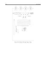
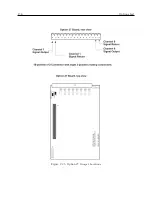
Page 196: ...176 Options List Figure C 25 Option 27 Jumper Locations ...
Page 214: ...194 Options List Figure C 28 Option 29 Connector Signal Locations ...
Page 270: ...250 Options List ...


