210
Options List
System Configure Password
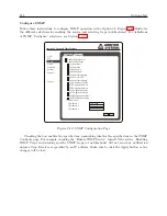
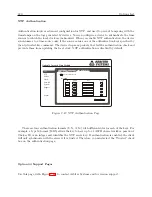
To configure the system password follow these instructions. From Figure C.32, select the Password
tab. Figure C.34 shows where to configure the System password. In the System page, click the
Password tab and fill in the current and new password. Click the Apply button. Password char-
acters must be from ASCII 33 to ASCII 126, and passwords may be from 1 to 16 characters in
length. Remember to write down any new password and keep it in a safe place.
Apply
Reset
Current Password
New Password
Confirm New Password
Figure C.34: Configure System Password
System Update
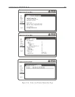
Update packages may include uploading more than one file to the Option 34. Make sure to follow the
instructions included with the update packages, and follow these instructions. From Figure C.32,
select the Update tab and click the Choose File button shown in Figure C.35. This should open
your file browser in which you should be able to locate the file package obtained from Arbiter
Systems. Click the Update button and the file should load to the Option 34. After uploading the
package the Option 34 must be rebooted for the changes to take effect.
Make sure that the computer
and clock do not lose power during the upload process.
Upload
Reset
Upload Package File
Choose File
no file selected
Figure C.35: Update System Firmware Package
Summary of Contents for 1088A
Page 4: ...iv ...
Page 6: ...vi ...
Page 18: ...xviii LIST OF FIGURES ...
Page 23: ...1 4 Attaching Rack Mount Ears to 1088A B Series Clocks 3 Figure 1 2 Attaching Rack Mount Ears ...
Page 24: ...4 Unpacking the Clock ...
Page 32: ...12 Front and Rear Panels ...
Page 38: ...18 Connecting Inlet Power Input and Output Signals ...
Page 46: ...26 GPS Antenna and Cable Information ...
Page 48: ...28 Setting Internal Jumpers Figure 5 1 Model 1088B Main Board ...
Page 76: ...56 The Setup Menus ...
Page 112: ...92 Serial Communication and Command Set ...
Page 127: ...B 4 Physical Dimensions 107 Figure B 1 Suggested Mounting of the AS0094500 Surge Arrester ...
Page 128: ...108 Using Surge Arresters ...
Page 145: ...C 5 Option 04 Parallel BCD Output 125 Figure C 4 Option 04 Output Jumper Settings ...
Page 146: ...126 Options List Figure C 5 Option 04 Board Layout and Jumper Locations ...
Page 166: ...146 Options List Figure C 12 Option 17 Board Layout and Jumper Locations ...
Page 187: ...C 16 Option 20A Four Fiber Optic Outputs 167 Figure C 22 Option 20A Jumper Locations ...
Page 194: ...174 Options List Figure C 24 Option 23 Internal Jumper Setup ...
Page 196: ...176 Options List Figure C 25 Option 27 Jumper Locations ...
Page 214: ...194 Options List Figure C 28 Option 29 Connector Signal Locations ...
Page 270: ...250 Options List ...

