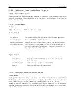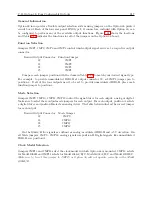
C.23 Option 36: Four Configurable Outputs
249
Output Signal
Function Select Jumper
Mode Select Jumper
IRIG-B Modulated
1
B
Deviation
2
B
IRIG-B Unmodulated
3
A
IRIG-E
4
A
IRIG-H
5
A
10 MPPS
6
A
5 MPPS
7
A
1 MPPS
8
A
100 kPPS
9
A
10 kPPS
10
A
1 kPPS
11
A
100 PPS
12
A
60 PPS
13
A
50 PPS
14
A
10 PPS
15
A
IRIG-D/1 PPM
16
A
1 PPM
17
A
1 PPS
18
A
Programmable Pulse
19
A
Out of Lock
20
A
IRIG-B Mod. Manch.
21
A
No Connection
22
A
Table C.18: Option 36 Output Connector Jumper Settings
NOTE: If any of the jumpers were changed, replace the cover to the chassis before returning to
service.
Summary of Contents for 1088A
Page 4: ...iv ...
Page 6: ...vi ...
Page 18: ...xviii LIST OF FIGURES ...
Page 23: ...1 4 Attaching Rack Mount Ears to 1088A B Series Clocks 3 Figure 1 2 Attaching Rack Mount Ears ...
Page 24: ...4 Unpacking the Clock ...
Page 32: ...12 Front and Rear Panels ...
Page 38: ...18 Connecting Inlet Power Input and Output Signals ...
Page 46: ...26 GPS Antenna and Cable Information ...
Page 48: ...28 Setting Internal Jumpers Figure 5 1 Model 1088B Main Board ...
Page 76: ...56 The Setup Menus ...
Page 112: ...92 Serial Communication and Command Set ...
Page 127: ...B 4 Physical Dimensions 107 Figure B 1 Suggested Mounting of the AS0094500 Surge Arrester ...
Page 128: ...108 Using Surge Arresters ...
Page 145: ...C 5 Option 04 Parallel BCD Output 125 Figure C 4 Option 04 Output Jumper Settings ...
Page 146: ...126 Options List Figure C 5 Option 04 Board Layout and Jumper Locations ...
Page 166: ...146 Options List Figure C 12 Option 17 Board Layout and Jumper Locations ...
Page 187: ...C 16 Option 20A Four Fiber Optic Outputs 167 Figure C 22 Option 20A Jumper Locations ...
Page 194: ...174 Options List Figure C 24 Option 23 Internal Jumper Setup ...
Page 196: ...176 Options List Figure C 25 Option 27 Jumper Locations ...
Page 214: ...194 Options List Figure C 28 Option 29 Connector Signal Locations ...
Page 270: ...250 Options List ...


