C.4 Option 03: Four Additional Outputs -
Obsolete
113
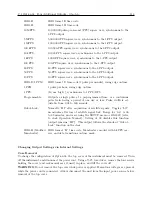
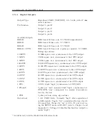
IRIG-E:
IRIG format E time code.
IRIG-H:
IRIG format H time code.
10 MPPS:
10,000,000 pulse-per-second (PPS) square wave, synchronous to the
1-PPS output.
5 MPPS:
5,000,000-PPS square wave, synchronous to the 1-PPS output.
1 MPPS:
1,000,000-PPS square wave, synchronous to the 1-PPS output.
100 kPPS:
100,000-PPS square wave, synchronous to the 1-PPS output.
10 kPPS:
10,000-PPS square wave, synchronous to the 1-PPS output.
1 kPPS:
1,000-PPS square wave, synchronous to the 1-PPS output.
100 PPS:
100-PPS square wave, synchronous to the 1-PPS output.
60 PPS:
60-PPS square wave, synchronous to the 1-PPS output.
50 PPS:
50-PPS square wave, synchronous to the 1-PPS output.
10 PPS:
10-PPS square wave, synchronous to the 1-PPS output.
IRIG-D/1 PPM:
IRIG format D time code (1 pulse per minute), rising edge on time.
1 PPH:
1 pulse per hour, rising edge on time.
1 PPS:
(10 ms “high”), synchronous to 1 PPS/GPS.
Programmable:
Outputs a single pulse at a preprogrammed time, or a continuous
pulse train having a period of one day or less. Pulse width is ad-
justable from 0.01 to 600 seconds.
Out-of-Lock:
Normally “HI” after acquisition of satellite signals. Toggles “LO”
nn minutes after loss of satellite signal lock. Range for “nn” is 00
to 99 minutes, and is set using the SETUP menu or RS-232C (refer
to clock Operation Manual). Setting of 00 disables this function
(output remains “HI”). This output follows the standard “Out-of-
Lock” function on the clock.
IRIG-B (Modified
Manchester):
IRIG format “B” time code, Manchester encoded with 1-kPPS car-
rier, and data transitions on time mark.
Changing Output Settings via Internal Settings
Case Removal
To change the configuration of Option 03, the top cover of the instrument must be removed. Turn
off the instrument, and disconnect the power cord. Using a T-25 torx driver, remove the four screws
holding the cover (and rack mount ears, if used) in place, and lift the cover off.
WARNING
Do not remove the top cover while power is applied. Hazardous voltages are present
while the power cord is connected. Always disconnect the unit from the input power source before
removal of the top cover.
Summary of Contents for 1088A
Page 4: ...iv ...
Page 6: ...vi ...
Page 18: ...xviii LIST OF FIGURES ...
Page 23: ...1 4 Attaching Rack Mount Ears to 1088A B Series Clocks 3 Figure 1 2 Attaching Rack Mount Ears ...
Page 24: ...4 Unpacking the Clock ...
Page 32: ...12 Front and Rear Panels ...
Page 38: ...18 Connecting Inlet Power Input and Output Signals ...
Page 46: ...26 GPS Antenna and Cable Information ...
Page 48: ...28 Setting Internal Jumpers Figure 5 1 Model 1088B Main Board ...
Page 76: ...56 The Setup Menus ...
Page 112: ...92 Serial Communication and Command Set ...
Page 127: ...B 4 Physical Dimensions 107 Figure B 1 Suggested Mounting of the AS0094500 Surge Arrester ...
Page 128: ...108 Using Surge Arresters ...
Page 145: ...C 5 Option 04 Parallel BCD Output 125 Figure C 4 Option 04 Output Jumper Settings ...
Page 146: ...126 Options List Figure C 5 Option 04 Board Layout and Jumper Locations ...
Page 166: ...146 Options List Figure C 12 Option 17 Board Layout and Jumper Locations ...
Page 187: ...C 16 Option 20A Four Fiber Optic Outputs 167 Figure C 22 Option 20A Jumper Locations ...
Page 194: ...174 Options List Figure C 24 Option 23 Internal Jumper Setup ...
Page 196: ...176 Options List Figure C 25 Option 27 Jumper Locations ...
Page 214: ...194 Options List Figure C 28 Option 29 Connector Signal Locations ...
Page 270: ...250 Options List ...


