


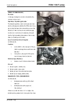


with the key ON and the sensor connector disconnected, check if there is battery voltage at
PIN 4: if NOT OK, check the continuity of the Red//Brown cable between the probe connector
and the injection relay (no. 33 in the electrical circuit diagram, position under the saddle,
close to the battery positive; however, CHECK the relay identification with the cable colours);
if there are also errors regarding the coils, lower and upper injectors and secondary air,
check the relay and its energy and power line; if there is voltage at PIN 4, check ground
insulation of the green cable (PIN 3): if NOT OK, restore the wiring harness; if OK, check
the continuity of the Green cable (between PIN 3 of the sensor connector and ENGINE PIN
32) and restore the wiring harness.
WARNING
The control unit does not detect the following malfunctions of the lambda probe circuit relative
to the signal: interrupted circuit, short circuit to ground or malfunction of the sensor (for ex-
ample, voltage not variable). If the indication is abnormal, perform the troubleshooting indicated
below.
Troubleshooting
•
Check the continuity of the circuit from the probe connector (PIN 1 and PIN 2) towards the
probe: replace the lambda probe if there is no continuity; if there is continuity, check the
sensor connector and the Marelli control unit connector: if NOT OK, restore; if OK, check
the continuity between the ENGINE connector PIN 10 and PIN 22 and restore the wiring
harness.
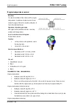
DIAGNOSTIC TOOL: LOGIC ERRORS
P0134 Rear bank lambda probe
Functional diagnosis:
•
no switching from high / no switching from low
Error cause:
•
If no switching from high: is shown when the ratio control is in closed loop and when the
secondary air valve is not operating. The error is validated if the engine is in CUTOFF status
and the probe signal is close to 1V, or if the engine is in another operating condition that
requires the injection but the switching from the"HIGH RATIO" to "LOW RATIO" is missing
for a certain"adjusted" number of dead points (PMS or TDC).
•
If no switching from low: is shown when the ratio control is in closed loop and when the
secondary air valve is not operating. The error is validated if during the ratio control stage,
the switching from "HIGH RATIO" to "LOW RATIO" is missing for a certain"adjusted" number
of upper dead points (PMS or TDC).
The instrument panel indicates this error by lighting up in a fixed manner the MI warning light.
Troubleshooting:
RSV4 1100 Factory
Electrical system
ELE SYS - 171
Summary of Contents for RSV4 1100 Factory
Page 1: ...SERVICE STATION MANUAL 2Q000401 RSV4 1100 Factory ...
Page 4: ......
Page 6: ...INDEX OF TOPICS CHARACTERISTICS CHAR ...
Page 55: ...INDEX OF TOPICS SPECIAL TOOLS S TOOLS ...
Page 63: ...INDEX OF TOPICS MAINTENANCE MAIN ...
Page 89: ...INDEX OF TOPICS ELECTRICAL SYSTEM ELE SYS ...
Page 245: ...INDEX OF TOPICS ENGINE FROM VEHICLE ENG VE ...
Page 270: ...INDEX OF TOPICS ENGINE ENG ...
Page 384: ...INDEX OF TOPICS POWER SUPPLY P SUPP ...
Page 387: ... Remove the fuel pump Injection RSV4 1100 Factory Power supply P SUPP 387 ...
Page 393: ...INDEX OF TOPICS SUSPENSIONS SUSP ...
Page 417: ...INDEX OF TOPICS CHASSIS CHAS ...
Page 455: ...INDEX OF TOPICS BRAKING SYSTEM BRAK SYS ...
Page 457: ...Operating diagram ABS functional diagram key RSV4 1100 Factory Braking system BRAK SYS 457 ...
Page 488: ...INDEX OF TOPICS COOLING SYSTEM COOL SYS ...
Page 499: ...INDEX OF TOPICS BODYWORK BODYW ...
Page 540: ...INDEX OF TOPICS PRE DELIVERY PRE DE ...
Page 546: ... Fit the two seater saddle Pre delivery RSV4 1100 Factory PRE DE 546 ...