


BEFORE STARTING ANY TROUBLESHOOTING PROCEDURES ON THE VEHICLE, CHECK THAT
THE BATTERY VOLTAGE IS ABOVE 12V.
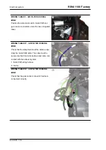
CONNECTOR CHECK PROCEDURE
The procedure includes the following checks:
1. Observation and check of the connector correct
position on the component or on the coupling con-
nector, making sure that the locking catch is re-
leased.
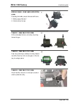
2. Observation of the terminals on the connector:
no rust marks or dirt should be present and it is
important to check terminal correct positioning on
the connector (i.e., all terminals aligned at the
same depth) and terminal integrity (i.e., that termi-
nals are not loose, open/bent, etc.). For connec-
tors whose terminals are not visible (e.g. Marelli
control unit) use a metal cable of suitable diameter
and introduce it carefully in the connector slot at
the same depth as for the other terminals of the
connector.
CAUTION
IN THE CASE OF SPORADIC FAULTS, MOVE OR WIGGLE
THE RELATIVE WIRING HARNESS SLIGHTLY WHILE PER-
FORMING EACH OF THE CHECKS INDICATED FOR TROU-
BLESHOOTING.
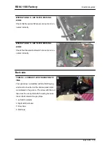
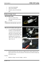
3. Pull cables gently from the back of the connector to check that the terminals are fitted correctly on
the connector and that the wires are fastened correctly to the terminals.
Checking electrical CONTINUITY
Purpose of check:
the purpose of this check is ensure that there are no interruptions or excess re-
sistance (due to corroded terminals, for example) in the circuit under inspection.
Tester:
set the tester selector to the "continuity" symbol and place the probes of the tested at the two
ends of the circuit. Normally, the tester will sound an audible signal to confirm continuity in the section
of circuit tested. Continuity may also be tested by setting the tester selector to the "Ohm" symbol and
checking that the resistance in the circuit is zero or of a few tenths of an Ohm.
IMPORTANT: THE CIRCUIT MUST BE UNPOWERED DURING THIS TEST. IF THE CIRCUIT IS
POWERED, THE RESULTS OF THIS TEST ARE MEANINGLESS.
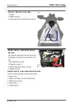
Checking GROUND CONNECTION
Purpose of check:
the purpose of this check is to verify that a cable or circuit is correctly connected
to the ground (-) of the vehicle.
Tester: set the tester selector to the "continuity" symbol and place one of the tester probes on the vehicle
ground point (or on the battery negative pole) and the other probe on the cable under inspection. Nor-
RSV4 1100 Factory
Electrical system
ELE SYS - 127
Summary of Contents for RSV4 1100 Factory
Page 1: ...SERVICE STATION MANUAL 2Q000401 RSV4 1100 Factory ...
Page 4: ......
Page 6: ...INDEX OF TOPICS CHARACTERISTICS CHAR ...
Page 55: ...INDEX OF TOPICS SPECIAL TOOLS S TOOLS ...
Page 63: ...INDEX OF TOPICS MAINTENANCE MAIN ...
Page 89: ...INDEX OF TOPICS ELECTRICAL SYSTEM ELE SYS ...
Page 245: ...INDEX OF TOPICS ENGINE FROM VEHICLE ENG VE ...
Page 270: ...INDEX OF TOPICS ENGINE ENG ...
Page 384: ...INDEX OF TOPICS POWER SUPPLY P SUPP ...
Page 387: ... Remove the fuel pump Injection RSV4 1100 Factory Power supply P SUPP 387 ...
Page 393: ...INDEX OF TOPICS SUSPENSIONS SUSP ...
Page 417: ...INDEX OF TOPICS CHASSIS CHAS ...
Page 455: ...INDEX OF TOPICS BRAKING SYSTEM BRAK SYS ...
Page 457: ...Operating diagram ABS functional diagram key RSV4 1100 Factory Braking system BRAK SYS 457 ...
Page 488: ...INDEX OF TOPICS COOLING SYSTEM COOL SYS ...
Page 499: ...INDEX OF TOPICS BODYWORK BODYW ...
Page 540: ...INDEX OF TOPICS PRE DELIVERY PRE DE ...
Page 546: ... Fit the two seater saddle Pre delivery RSV4 1100 Factory PRE DE 546 ...


