


CHAPTER 5. OPERATING INSTRUCTIONS
HF-2500A HIGH FREQUENCY WELD CONTROL
990-371
5-13
Section IV. Active Part Conditioning
1.
Press the
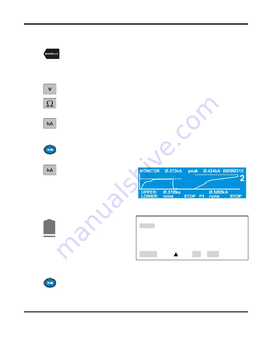
SCHEDULE
key, then select a Weld Schedule using
either
the
▲▼
arrows
or
the numeric keypad.
2.
Program a single pulse for
Constant Power
operation. Program the power level and weld time
to cause slight sticking between the two parts. Make a few welds and pull them apart. Increase
or decrease the power setting until a light tack weld is achieved.
3.
From the
MONITOR
keys section on the front panel, press the voltage
V
key and observe
the high peak of the voltage waveform.
4.
From the
MONITOR
keys section on the front panel, press the
Ω
(resistance) key and
observe the resistance waveform. This should appear to begin high, then start to drop as
a tack weld is made and oxides are removed.
5.
From the
MONITOR
keys section on the front panel, press the
kA
(current) key and observe
the current waveform starting to rise as the oxidization breaks down. If the current
waveform starts to flatten, this is an indication that the resistance has stabilized and the
parts have come into closer contact.
6.
Push
RUN
and optimize the energy and time setting of Pulse 1 (constant power) to provide
an adequate tack weld and also a current waveform (view in the monitor screen) that has
started to flatten out, but is still rising. This indicates that a full melt has not yet occurred.
7.
From the
MONITOR
keys section
on the front panel, press the
kA
key to program an upper current
limit on the
MONITOR
screen.
NOTE
: You can toggle between
PEAK
and
AVERAGE
readings by pressing the
PEAK/AVERAGE
key.
8.
9.
Press the
COOL
weld period
key. This will bring up the
PULSE 1 OUT OF LIMITS
ACTION
screen.
Select
4. PART CONDITIONER
(Stop Pulse1)
PULSE 1 OUT OF LIMITS ACTION
1. none
2. STOP WELD
3. INHIBIT PULSE 2
4. PART CONDITIONER (Stop Pulse1)
NUMBER Select,
Page, RUN or MENU
NOTE:
For more details on this process, see
Active Part Conditioner
in
Chapter 4, Using
Feedback Modes and Weld Monitoring.
10.
Since different levels of oxide require different amounts of time to reach the current limit,
return to the
RUN
screen and extend the programmed weld time (usually double the time
works). This will ensure that there will be enough time for the current to rise and reach
the limit, even with heavily oxidized parts.
Summary of Contents for HF-2500A
Page 1: ...990 371 REV J HIGH FREQUENCY WELD CONTROL HF 2500A OPERATION MANUAL...
Page 88: ......
Page 100: ......
Page 118: ......
Page 144: ......