


CIP Axis Attributes
Chapter 4
Rockwell Automation Publication MOTION-RM003I-EN-P - February 2018
233
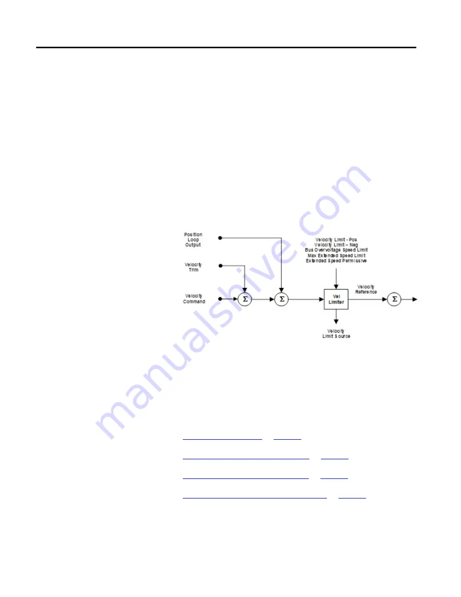
Velocity Limiter Behavior Diagram
The following diagram shows the extensions that have been added to the Velocity
Limiter to help manage the inherent risks of high speed PM motor operation. In
addition to the existing Velocity Limit - Positive/Negative attributes that can be
used to limit the Velocity Reference signal, two new limits have been defined based
on S
OV
and S
m
defined above. Specifically, the PM Motor Rotary - Bus Overvoltage
Speed and PM Motor Linear Bus Overvoltage Speed attributes establish an
absolute limit on the Velocity Reference signal that corresponds to S
OV
. This speed
limit can only be exceeded if the PM Motor Extended Speed Permissive attribute
is set to True. The PM Motor Rotary Max Extended Speed and PM Motor Linear
Max Extended Speed attributes establish an absolute limit on the Velocity
Reference signal that corresponds to S
m
. The Velocity Limit function limits the
Velocity Reference signal to the minimum of these attribute values. The Velocity
Limit Source attribute indicates the source of the velocity limit.
Through these extensions to the Velocity Limiter function, a drive that supports
field weakening can be configured to safely manage extended speed operation, only
allowing operation above S
OV
by setting the PM Motor Extended Speed Permissive
attribute. Systems that can run safely above S
OV
are generally equipped with a DC
Bus Regulator or a Resistive Brake Module.
See also
Position Loop Configuration Attributes
Velocity Loop Configuration Attributes
General Permanent Magnet Motor Attributes
These attribute tables contain attributes associated with general data about to a
Motion Control Axis Object instance.
Data Attributes