


Behavior models used in CIP Motion
Chapter 2
Rockwell Automation Publication MOTION-RM003I-EN-P - February 2018
61
reason feedforward is not recommended for point-to-point positioning
applications.
See also
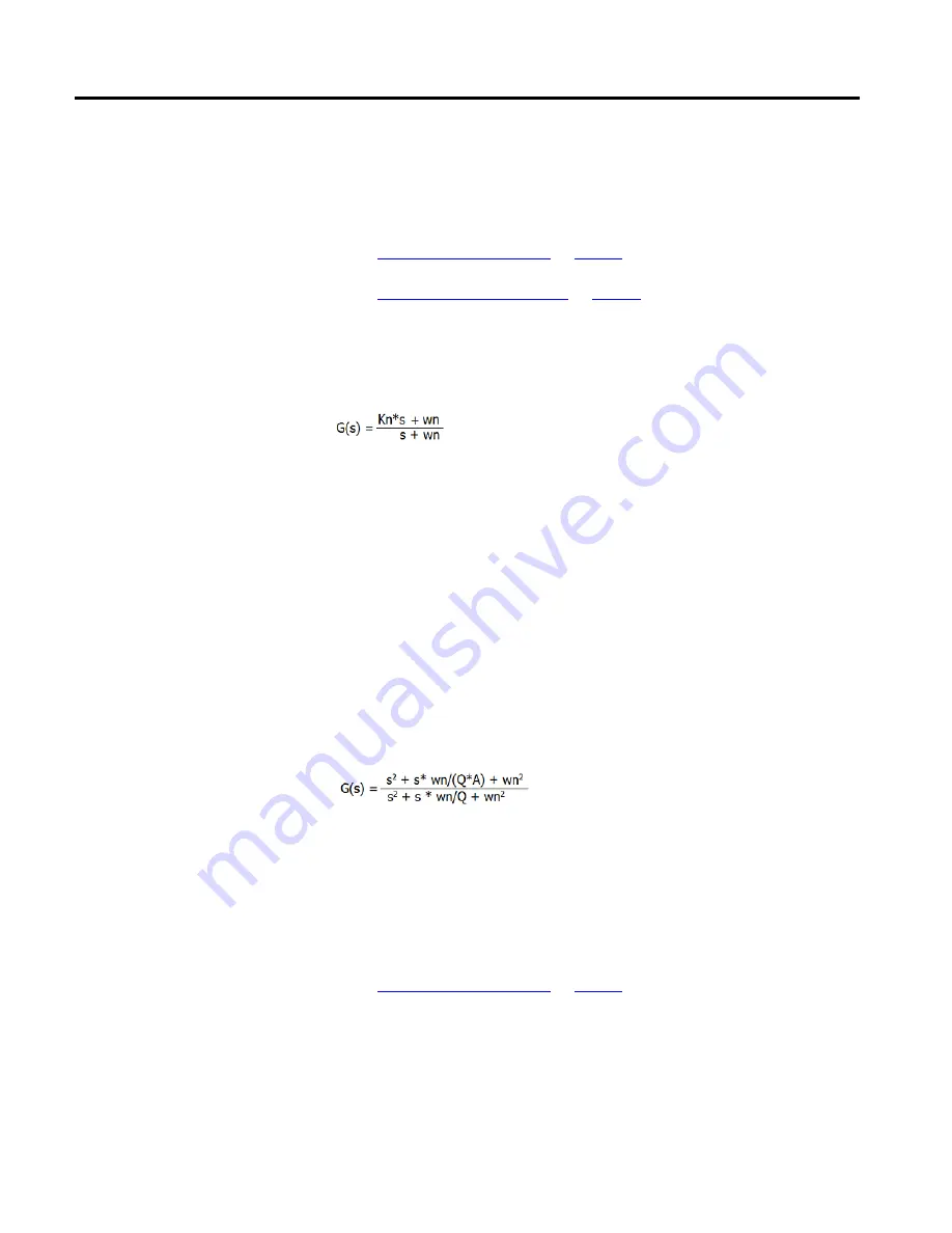
A lead-lag filter is provided at the output of the position loop forward path. This
filter can be used in the lead configuration to boost position loop bandwidth and
increase the stiffness, for example, the ability to resist dynamic load disturbances.
In this equation, Kn represents the Lead-Lag Filter Gain, or high frequency gain of
the filter (the low frequency gain is always 1), and wn represents the Lead-Lag
Filter Bandwidth associated with the pole of the filter:
•
If Kn > 1, the filter provides lead compensation.
•
If Kn < 1, the filter provides lag compensation.
•
If Kn = 0 the lead-lag filter becomes a pure low pass filter.
•
If Kn = 1, the filter is disabled.
Finally, a notch filter is included that has been shown to be effective in solving
certain types mechanical compliance problems. The equation for this filter is as
follows:
In this equation, Q represents the sharpness of the notch, and A represents the
attenuation depth of the notch. In most implementations, the sharpness, Q, and
the attenuation depth, A, are hard-coded in the device. In PowerFlex drives the
value of Q is 0.62 and the depth is set to 30.
See also
The Motion Control Axis state model includes the following the states and state
transitions.
Off State
This is the state of the Motion Control Axis with power off.
Position Loop Output Filters
State Behavior