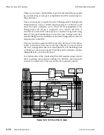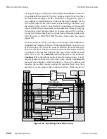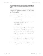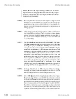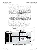
I/P KA
and
I/P KB:
Use these inputs only if you are feeding
serial component digital key signals to the A28 that are
cotimed to the 8150 program or preview output. Note that
the A28 encodes only one input key signal at a time.
STEP 12:
Connect power to the A28. Verify that a composite version of
the 8150 output is present at all A28 video outputs. If Option
G is installed, you can adjust the levels and horizontal timing
of the analog outputs in a limited range, if needed, to match
you system’s levels and horizontal timing.
NOTE: If you use the A28 to encode sources other than the
8150 set to 34 lines of delay, you must set DIP switch U15Q
segment 1 OFF. This setting, however, prevents using it to
encode the 8150 output with the correct timing, unless the
8150 output is set to one frame delay. See the A28 Technical
Manual for more information on this DIP switch and other
A28 timing controls.
Encoding the 8150 Output (NTSC)
8150 Technical Guide
5-88
Engineering Setup
9100-0212-04 - May 2000
Summary of Contents for ASWR8150
Page 12: ...Table of Contents 8150 Technical Guide X Contents 9100 0212 04 May 2000...
Page 39: ......
Page 80: ...Control Panel Connector Detail 8150 Technical Guide 2 40 Installation 9100 0212 04 May 2000...
Page 109: ...Option Installation 8150 Technical Guide 3 30 Option Installation 9100 0212 04 May 2000...
Page 236: ...8150 Partial Parts List 8150 Technical Guide A 6 Appendix 9100 0212 04 May 2000...

