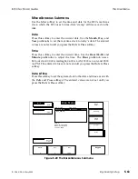
STEP 5:
Tilt the top edge of the Control Panel LCD panel toward you,
letting the bottom edge rest on the bottom edge of the Control
Panel. Inside the Control Panel, there are four cables that you
must disconnect from the CPU assembly if you want to
completely separate the two Control Panel sections. These
cables are:
DC Power (J7), in the lower right portion of the board
Floppy Disk (J3), at the right edge of the board
LCD Data (P6), in the upper right portion of the board
CPU Data/Address (J4), at the center lower edge of the board
STEP 6:
After disconnecting the above cables from the CPU board, lift
the Control Panel top piece completely off and set it aside.
Reassembling the Control Panel Top and Bottom
STEP 1:
You may want to place a piece of cloth or plastic along lower
edge of the Control Panel bottom to avoid scratching the
paint. Place the Control Panel top on top of the bottom, tilting
the LCD panel up toward you.
STEP 2:
Reconnect the four cables to the CPU board:
DC Power (J7), in the lower right portion of the board
Floppy Disk (J3), at the right edge of the board
LCD Data (P6), in the upper right portion of the board
CPU Data/Address (J4), at the center lower edge of the board
STEP 3:
Lift and hold the Control Panel top piece above the bottom
piece and tilt the right side down slightly. Lower the top piece
so that the floppy disk drive fits into its cutout in the bottom
piece. Continue lowering the top piece until it fits into place
on the bottom piece.
STEP 4:
Hold the two pieces together, and turn the Control Panel face
down on the cloth or plastic. Reinstall the 10 flat head screws
in the Control Panel bottom.
Assembly Removal /Replacement
8150 Technical Guide
5-72
Engineering Setup
9100-0212-04 - May 2000
Summary of Contents for ASWR8150
Page 12: ...Table of Contents 8150 Technical Guide X Contents 9100 0212 04 May 2000...
Page 39: ......
Page 80: ...Control Panel Connector Detail 8150 Technical Guide 2 40 Installation 9100 0212 04 May 2000...
Page 109: ...Option Installation 8150 Technical Guide 3 30 Option Installation 9100 0212 04 May 2000...
Page 236: ...8150 Partial Parts List 8150 Technical Guide A 6 Appendix 9100 0212 04 May 2000...

