Module Options
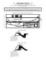
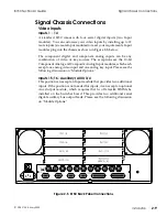
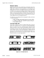
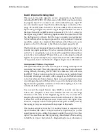
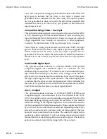
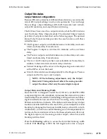
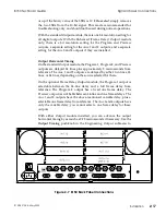
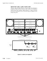
Figure 2-6, below, shows the available Input and Output modules. The
Digital Input modules are full 10-bit compatible, with 8-bit paths for the
digital inputs selectable in the Engineering menu. The Digital Input
modules also have one color matte generator per input that you can use
as a fill source for borders, keys, backgrounds, etc., instead of the input
signal. You can select and adjust the matte generators in the Engineering
menu. The Analog Input modules do not have matte generators, but
provide gain and horizontal picture position adjustments for each input.
These adjustments are in the Engineering menu.
For information on installing and removing Input modules, see Section
3 – Option Installation.
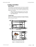
NOTE: All eight input module locations must have either
a module or a blank plate installed for proper cooling air
flow inside the chassis.
Dual Serial Digital Input
This module conforms to CCIR 601/SMPTE 259M serial component
digital video standards. Input "A" connectors are odd numbered inputs;
input "B" connectors are even numbered inputs. Input horizontal
retiming is automatic, with a range of one half line advanced to two lines
delayed from reference. Dual color LEDs appear through an opening
near each BNC connector. These LEDs light green to indicate that the
input is correct and genlocked. Yellow indicates that the input is not
genlocked or does not match the system line standard. Unlit LEDs
indicate that there is no input signal present.
Figure 2-6 I/O Module Options
Signal Chassis Connections
8150 Technical Guide
2-10
Installation
9100-0212-04 - May 2000
Summary of Contents for ASWR8150
Page 12: ...Table of Contents 8150 Technical Guide X Contents 9100 0212 04 May 2000...
Page 39: ......
Page 80: ...Control Panel Connector Detail 8150 Technical Guide 2 40 Installation 9100 0212 04 May 2000...
Page 109: ...Option Installation 8150 Technical Guide 3 30 Option Installation 9100 0212 04 May 2000...
Page 236: ...8150 Partial Parts List 8150 Technical Guide A 6 Appendix 9100 0212 04 May 2000...

