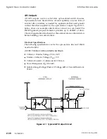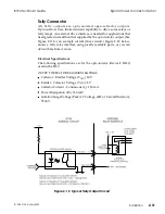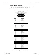
Signal Chassis Connector Detail
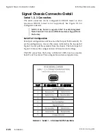
Serial 1, 2, 3 Connectors
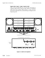
The serial connectors can be configured for RS-422 master or slave
operation (RS-232 format is not supported). See Figure 2-8 for
configuration details.
NOTE: Only Serial 3 supports LINC (Locally Integrated
Node Control). It is set as an RS-422 master as shipped from
the factory.
Serial Port Configuration
Serial port configuration switches are on the Output/Tally assembly. To
set the configurations, remove the screws indicated in the top part of
Figure 2-8, and pull the assembly from the chassis. The bottom part of
Figure 2-8 shows the configuration switch location and settings.
The 8150 comes from the factory with Serial 3 (LINC) set as a master,
Serial 1 and 2 as slaves. This configuration suits most applications.
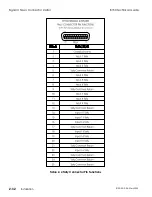
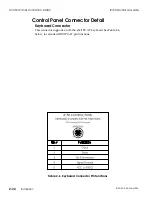
Table 2-1 Serial 1 - 3 Connector Pin Functions
Signal Chassis Connector Detail
8150 Technical Guide
2-26
Installation
9100-0212-04 - May 2000
Summary of Contents for ASWR8150
Page 12: ...Table of Contents 8150 Technical Guide X Contents 9100 0212 04 May 2000...
Page 39: ......
Page 80: ...Control Panel Connector Detail 8150 Technical Guide 2 40 Installation 9100 0212 04 May 2000...
Page 109: ...Option Installation 8150 Technical Guide 3 30 Option Installation 9100 0212 04 May 2000...
Page 236: ...8150 Partial Parts List 8150 Technical Guide A 6 Appendix 9100 0212 04 May 2000...

