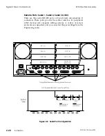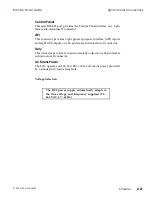
Control Panel
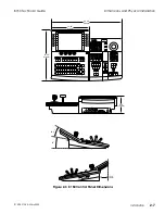
Figure 2-3, on the facing page, shows the dimensions of the 8150 Control
Panel for desk top installation.
Top View
The top view shows overall Control Panel dimensions.
Back View
The back view shows the Control Panel height from the base to the
highest point.
Left/Side View
The left/side view shows the angle between the Control Panel base and
the button surface, and from the base to the LCD display surface.
Right/Side View
The right/side view shows the location of the floppy disk drive and the
clearance from the Control Panel base rear edge to the LCD display rear
edge.
Control Panel Cutout Dimensions
If you are mounting your Control Panel in a console, please see the 3D
Control Panel drawing at the back of this publication. Several views
show console cutout dimensions.
Dimensions and Physical Installation
8150 Technical Guide
2-6
Installation
9100-0212-04 - May 2000
Summary of Contents for ASWR8150
Page 12: ...Table of Contents 8150 Technical Guide X Contents 9100 0212 04 May 2000...
Page 39: ......
Page 80: ...Control Panel Connector Detail 8150 Technical Guide 2 40 Installation 9100 0212 04 May 2000...
Page 109: ...Option Installation 8150 Technical Guide 3 30 Option Installation 9100 0212 04 May 2000...
Page 236: ...8150 Partial Parts List 8150 Technical Guide A 6 Appendix 9100 0212 04 May 2000...

