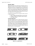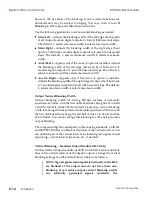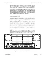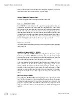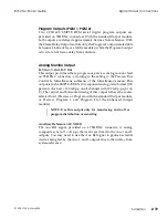
however, the rise times of the blanking-to-active video transitions are
unfiltered and may be subject to ringing. You may wish to turn
H
Blanking
to
ON
to properly filter these transitions.
Use the following pushknobs to set horizontal blanking as needed:
Main Left –
Adjusts the blanking width of the left edge (back porch)
of all Output module digital outputs in 2-pixel (148 nsecond) steps.
The default, 1, selects minimum width; 4 selects maximum width.
Main Right –
Adjusts the blanking width of the right edge (front
porch) of all Output module digital outputs in 2-pixel (148 nsecond)
steps. The default, 1, selects minimum width; 4 selects maximum
width.
Aux 3/4 Left –
Appears only if the Aux 3/4 option is installed. Adjusts
the blanking width of the left edge (back porch) of both Aux 3/4
module digital outputs in 2-pixel (148 nsecond) steps. The default, 1,
selects minimum width; 4 selects maximum width.
Aux 3/4 Right –
Appears only if the Aux 3/4 option is installed.
Adjusts the blanking width of the right edge (front porch) of both Aux
3/4 module digital outputs in 2-pixel (148 nsecond) steps. The default,
1, selects minimum width; 4 selects maximum width.
Output Vertical Blanking Width
Vertical blanking width for analog 525-line systems is nominally
specified as 20 lines, with the first unblanked lines being line 21 in field
1 and the last half of line 283 (20) in field 2. Likewise, vertical blanking
width for analog 625-line systems is nominally specified as 25 lines, with
the first unblanked lines being the last half of line 23 in field 1 and line
336 in field 2. You cannot change this blanking for the analog monitor
output blanking.
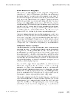
The component digital counterparts to these analog standards, CCIR 601
and SMPTE 125M, let you blank certain lines of the vertical interval. You
can unblank part of the vertical interval for inserting test signals, closed
captioning, vertical interval timecode, etc., if needed.
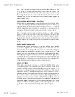
Vertical Blanking – Standard Output Module (8100 Only)
On the standard Output module, use DIP switch S2 to blank or unblank
lines in the vertical interval of the digital outputs. Change the vertical
blanking settings from the default (shown below) as follows.
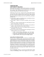
NOTE: Signals generated completely internally in the 8150
are blanked at the output and do not have their own
blanking. If you reduce output vertical blanking width,
any internally generated signals (primarily the
Signal Chassis Connections
8150 Technical Guide
2-14
Installation
9100-0212-04 - May 2000
Summary of Contents for ASWR8150
Page 12: ...Table of Contents 8150 Technical Guide X Contents 9100 0212 04 May 2000...
Page 39: ......
Page 80: ...Control Panel Connector Detail 8150 Technical Guide 2 40 Installation 9100 0212 04 May 2000...
Page 109: ...Option Installation 8150 Technical Guide 3 30 Option Installation 9100 0212 04 May 2000...
Page 236: ...8150 Partial Parts List 8150 Technical Guide A 6 Appendix 9100 0212 04 May 2000...

