background image

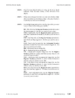
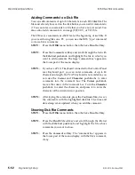
Delete

Press this softkey to access the 

File Type

 and 

File List 

pushknobs, which

let you select a file to delete. See the tutorial earlier in this section for a
step-by-step procedure.

Confirm

Press this softkey to execute the current command, in this case, a "copy
file" or "delete file" command.

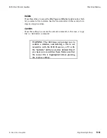
WARNING: The 8150 does not prompt you to
confirm a deletion, and deleting a file is not
reversible with the 8150. However, a PC with
the "undelete" utility can restore deleted files if
you have not overwritten them. Make sure that
the correct file is highlighted before pressing
the 

Confirm

 softkey.

8150 Technical Guide

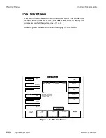
The Disk Menu 

9100-0212-04 - May 2000

Engineering Setup        

5-61

Summary of Contents for ASWR8150

Page 1: ...ASWR8150 Component Digital Switcher Technical Guide PN 9100 0212 04 Copyright May 2000 Accom Inc 1490 O Brien Drive Menlo Park California 94025...

Page 2: ...d in a commercial environment This equipment generates uses and can radiate radio frequency energy and if not installed and used in accordance with the technical and operations manuals may cause harmf...

Page 3: ...or Matte Generators 5 1 14 Super Matte Generator 6 1 14 Black Generator 7 1 14 Wipe Pattern Generators 8 1 16 Framestores 9 1 16 Key Monitor Selector 10 1 16 Mix Effect Processor 11 1 16 PGM PST DSK P...

Page 4: ...2 1 26 RS 422 1 26 Keyboard 1 26 External Floppy 1 26 Installation Unpacking 2 1 Pre Installation Checks 2 1 Signal Chassis 2 1 Control Panel 2 1 Power Consumption 2 1 Signal Chassis 2 1 Voltage Selec...

Page 5: ...el Digital Input 2 12 Aux 3 4 Output 2 12 Output Modules 2 13 Output Module Configurations 2 13 Output Module Connections 2 18 Auxiliary Outputs AUX 1 AUX 2 2 18 Preview Output PVW 2 18 Program Output...

Page 6: ...nnector Detail 2 34 Keyboard Connector 2 34 RS 232 Connector 2 35 RS 422 Connector 2 36 Control In Out Connectors 2 37 External Floppy Connector 2 38 Power Connector 2 39 Option Installation Option Id...

Page 7: ...E Board Jumpers and Modules 4 12 Control Panel 4 15 Menu Buttons 4 15 Menu Screen Layout Controls 4 16 Menu Display 4 16 Submenu Labels and Controls 4 16 The Keypad Buffer 4 17 Softkeys and Pushknobs...

Page 8: ...s 5 12 Proc Adjust Gain Pedstl 5 13 More Proc Adjust H Phase Ofs 5 13 Output Submenu 5 14 Output Delay 5 14 Output Bits 5 15 H Blanking 5 15 V Blanking 5 16 Output Phase 5 16 Key Mode 5 17 Miscellaneo...

Page 9: ...POs 5 42 Preview Monitor Overlays Submenu 5 43 Safe Action 5 43 Grid Overlay 5 43 Overlay Color 5 43 Reference Lines 5 44 Cursor 5 44 Cursor Ref Line Color 5 44 Disk Drive Operations 5 45 Setting the...

Page 10: ...mat 5 62 Confirm 5 62 Miscellaneous Submenu 5 63 Date 5 63 Time 5 63 Date Time 5 63 Assembly Removal Replacement 5 64 Power Supply Assembly Removal Replacement 5 64 Power Supply Output Voltage Adjustm...

Page 11: ...Timing Considerations 6 1 Introduction 6 1 System Locking Reference 6 2 Automatic Input Timing 6 2 Propagation Throughput Delay 6 2 Aux Output Sources Delayed by Two Lines 6 3 Aux Output Sources Dela...

Page 12: ...Table of Contents 8150 Technical Guide X Contents 9100 0212 04 May 2000...

Page 13: ...pport a variety of user selectable formats Functionally the 8150 has one Mix Effect bus with two keyers and a main Program Preset bus that incorporates a single downstream keyer with master fade to bl...

Page 14: ...ndependently there is no key channel in this mode Video Key you can control the video channel and key channel independently Video Key Shadow you can control the combined video key channel and the drop...

Page 15: ...EYFRAME RECALL KEYFRAME RECALL KEYFRAME FIELD ACQUIRE TIMELINE PREVIOUS NEXT STOP NEXT STOP NEXT REV RUN PATH PREVIEW PATH PREVIEW CURSOR CH B JOYSTICK LOCK JOYSTICK LOCK GLOBAL EFFECTS TRANS EFFECTS...

Page 16: ...2 An internal 32 input by 32 output crosspoint matrix routes all video sources in the 8150 A brief description of the matrix inputs and outputs appears below Crosspoint Matrix Inputs The following li...

Page 17: ...1 2 2 Figure 1 2 8150 Video Functional Diagram 8150 Technical Guide Video Processing Functional Description 9100 0212 04 May 2000 Introduction 1 5...

Page 18: ...ct Program as the Preview Source in the Miscellaneous menu Pvw Bus Ctrl Misc submenu and select DSK Preview as the source for the Aux bus output WIPE SEND Wipe Pattern Send Use the Mix Effect or Progr...

Page 19: ...2 2 Figure 1 3 8150 Video Functional Diagram 8150 Technical Guide Video Processing Functional Description 9100 0212 04 May 2000 Introduction 1 7...

Page 20: ...the 4 4 4 Chroma Key option is installed KEY 1 The key source selected for M E keyer 1 MASK The mask source selected for M E keyer 1 also used as the 0 2 2 part of the key feed if the 4 4 4 Chroma key...

Page 21: ...2 2 Figure 1 4 8150 Video Functional Diagram 8150 Technical Guide Video Processing Functional Description 9100 0212 04 May 2000 Introduction 1 9...

Page 22: ...either a full color or monochrome video signal INTERNAL DVE CH B TEXTURE SEND The source selected as the SurfaceFX texture input for channel B of the internal DVE option This source can be either a fu...

Page 23: ...3 3 Figure 1 5 8150 Video Functional Diagram 8150 Technical Guide Video Processing Functional Description 9100 0212 04 May 2000 Introduction 1 11...

Page 24: ...eds their respective Mix Effect or DSK keyer Key 1 Key 2 DSK and an associated suppression signal that feeds the optional Color Corrector Suppress 1 Suppress 2 Suppress DSK Key Processing All keyers a...

Page 25: ...4 4 Figure 1 7 8150 Video Functional Diagram 8150 Technical Guide Video Processing Functional Description 9100 0212 04 May 2000 Introduction 1 13...

Page 26: ...osition and defocus in both the horizontal and vertical dimensions Border Processing Keys can have the following types of borders full surround outline only embossed extruded trailing and drop shadow...

Page 27: ...5 Figure 1 8 8150 Video Functional Diagram 8150 Technical Guide Video Processing Functional Description 9100 0212 04 May 2000 Introduction 1 15...

Page 28: ...n route anywhere within or outside the 8150 You can also save and recall framestore images to and from the floppy disk drive or the optional internal SCSI hard disk drive Key Monitor Selector 10 The K...

Page 29: ...7 8 9 6 Figure 1 9 8150 Video Functional Diagram 8150 Technical Guide Video Processing Functional Description 9100 0212 04 May 2000 Introduction 1 17...

Page 30: ...mposite sync signal that provides locking reference for video devices typically DVEs fed by Aux bus outputs 1 and 2 because of their inherent delay from house reference Aux bus output timing varies ac...

Page 31: ...10 12 13 11 Figure 1 10 8150 Video Functional Diagram 8150 Technical Guide Video Processing Functional Description 9100 0212 04 May 2000 Introduction 1 19...

Page 32: ...and 2 See Section 6 System Timing for more information Component Analog Monitor Outputs Y R Y B Y You can select this monitor feed as Preview Program 1 or Program 2 video Its timing 34 line or frame d...

Page 33: ...13 Figure 1 11 8150 Video Functional Diagram 8150 Technical Guide Video Processing Functional Description 9100 0212 04 May 2000 Introduction 1 21...

Page 34: ...ormally independent of the Aux 1 and 2 outputs but you can zero time them to Aux 1 and 2 unless Aux 1 and 2 are set to frame delay by switching the Combiner setting On in the Engineering Input submenu...

Page 35: ...13 Figure 1 12 8150 Video Functional Diagram 8150 Technical Guide Video Processing Functional Description 9100 0212 04 May 2000 Introduction 1 23...

Page 36: ...422 cables The Control Panel maximum chain length is 2000 feet 610 meters for all Control Panels on the chain GPI General Purpose Interface This port supports eight inputs and eight outputs GPI input...

Page 37: ...Figure 1 13 8150 Control Functional Diagram 8150 Technical Guide Control Functional Description 9100 0212 04 May 2000 Introduction 1 25...

Page 38: ...rted Keyboard You canconnect an off the shelf PCATkeyboardtothisport fornaming crosspoints and disk files External Floppy This port connects an external 3 5 1 44MB floppy disk drive You will need this...

Page 39: ......

Page 40: ...devices are sensitive to static electricity andmay be damaged by static discharge Observe static precautions when handling any electronic components or assemblies Use only a soldering iron with a gro...

Page 41: ...ont cover and ensure the internal circuit board s is seated in the Motherboard Carefully inspect the Signal Chassis to ensure that no parts were dislodged during shipping Control Panel Carefully inspe...

Page 42: ...y into a standard AC mains outlet then connect the DC power cable to the Control Panel POWER connector The DC power cable is approximately six feet two meters long Voltage Selection The Control Panel...

Page 43: ...hes 152mm at the chassis rear for ventilation NOTE All eight input module locations must have either a module or a blank plate installed for proper cooling air flow inside the chassis Control Panel Th...

Page 44: ...he front cover is 1 44 inches 37mm Side View The side view shows the chassis height and rack support locations Rack space required is 7 0 inches 178mm or four rack units Three rack ear locations are a...

Page 45: ...Figure 2 2 Signal Chassis Dimensions 8150 Technical Guide Dimensions and Physical Installation 9100 0212 04 May 2000 Installation 2 5...

Page 46: ...nel base and the button surface and from the base to the LCD display surface Right Side View The right side view shows the location of the floppy disk drive and the clearance from the Control Panel ba...

Page 47: ...84 580mm 12 30 312mm 16 30 414mm 5 50 140mm 32 5 o 10 o 3 12 79mm Figure 2 3 8150 Control Panel Dimensions 8150 Technical Guide Dimensions and Physical Installation 9100 0212 04 May 2000 Installation...

Page 48: ...witcher files The figure below shows the dimensions for console mounting the optional external disk drive 4 8 122mm 8 0 203mm 1 0 25mm 0 5 12 7mm 4 0 101mm 5 3 134mm Mounting bracket adjustment range...

Page 49: ...ite Analog Input modules which each accept one analog video input and one analog key input Please see the following discussion on Module Options Inputs 15 16 Auxiliary AUX 3 4 This position can accept...

Page 50: ...ion 3 Option Installation NOTE All eight input module locations must have either a module or a blank plate installed for proper cooling air flow inside the chassis Dual Serial Digital Input This modul...

Page 51: ...odule provides one component analog video input and one analog key input The video input can be one of several component analog formats including SMPTE EBU N10 Betacam MII and wide band RGB The key in...

Page 52: ...A connectors are odd numbered inputs and input B connectors are even numbered inputs Input horizontal retiming is automatic with a range of one half line advanced to two lines delayed from reference...

Page 53: ...tch on the board 10 bit 8 bit resolution is set independently for the Program Preview outputs and for the Aux 1 and 2 outputs NOTE Of the following adjustments only the Output Horizontal Timing adjust...

Page 54: ...aximum width Output Vertical Blanking Width Vertical blanking width for analog 525 line systems is nominally specified as 20 lines with the first unblanked lines being line 21 in field 1 and the last...

Page 55: ...ts designated line pair if the switch is off it blanks its designated line pair Note that the switches only blank their designated line pairs and are otherwise independent of each other S2 Switch Sett...

Page 56: ...line plus its counterpart in Field 2 use the Select Line pushknob to select the line number whose blanking status you want to change then press the V Blanking softkey This toggles the Blanking Status...

Page 57: ...nd 2 outputs are delayed by either two lines 18 lines or 34 lines depending on the source selected for them On the optional Frame Delay Output module the Program 1 output is selectable between the 34...

Page 58: ...al CCIR 601 SMPTE 259M serial digital auxiliary bus output feeds are provided on 75 BNC connectors You can choose the output video source for each Aux output in the Miscellaneous menu Note that the co...

Page 59: ...s menu This output is in the SMPTE EBU N10 component analog video format 100 percent color bars 700 mVp p on all channels with 300 mVp p sync on Y The vertical and horizontal timing of this output fol...

Page 60: ...se ports provide the control interface for peripheral LINC devices and computer editing systems A variety of remote protocols are supported and you can select the port settings from the Engineering me...

Page 61: ...D connector Tally This connector provides 16 input source tally outputs on a 25 pin female sub miniature D connector AC Mains Power The 8150 operates on 100 120 220 or 240 volt mains power provided b...

Page 62: ...trol In This serial port connects the Control Panel to the Signal Chassis control chain It is a 9 pin female sub miniature D connector Control Out This serial port connects additional Control Panels t...

Page 63: ...nternal floppy disk drive Power The Control Panel receives DC operating voltages on this 8 pin female DIN connector Reset Button Pressing this button resets the CPU in the Control Panel only and does...

Page 64: ...De Acquiring Control When a single Control Panel 8150 system powers up the Control Panel automatically lights its ACQUIRE button right side of the Control Panel indicating that it has control of the S...

Page 65: ...ignal Chassis press the RESET button on the rear connector panel of the Control Panel to reboot it If after a reboot there is still no communication follow the steps outlined in the Control Panel menu...

Page 66: ...on Serial port configuration switches are on the Output Tally assembly To set the configurations remove the screws indicated in the top part of Figure 2 8 and pull the assembly from the chassis The bo...

Page 67: ...The Control Panel Control In connector is wired as an RS 422 slave port YoucanuseagenericRS 422cablewiredpin to pinfortheControlPanel connection Table 2 2 Control Panel Connector Pin Functions 8150 Te...

Page 68: ...re for the opto isolator device H11L1 used in the 8150 INPUT LED MAXIMUM RATINGS Reverse Voltage VR 6 V Continuous Forward Current IF 60 mA Peak Forward Current 300 Sec Pulse 1 2 A Forward Turn On Vol...

Page 69: ...Table 2 3 GPI Connector Pin Functions 8150 Technical Guide Signal Chassis Connector Detail 9100 0212 04 May 2000 Installation 2 29...

Page 70: ...mW of drive Check all applicable data sheets for the external devices shown below before building your current driver Electrical Specifications The following specifications are for the opto isolator d...

Page 71: ...lly relay interface using locally available parts or you can obtain them from Accom Electrical Specifications The following specifications are for the opto isolator device 4N33 used in the 8150 OUTPUT...

Page 72: ...Table 2 4 Tally Connector Pin Functions Signal Chassis Connector Detail 8150 Technical Guide 2 32 Installation 9100 0212 04 May 2000...

Page 73: ...e pin functions for the CCIR 656 SMPTE 125M parallel digital connectors on the Dual Parallel Input modules Table 2 5 Parallel Digital Connector Pin Functions 8150 Technical Guide Signal Chassis Connec...

Page 74: ...This connector supports an off the shelf PC AT keyboard See Table 2 6 below for standard IBM PC AT pin functions Table 2 6 Keyboard Connector Pin Functions Control Panel Connector Detail 8150 Technic...

Page 75: ...ces for fine control of wipe patterns when drawing masks in the framestore Table 2 7 below gives the pin function details for the RS 232 port Table 2 7 RS 232 Connector Pin Functions 8150 Technical Gu...

Page 76: ...ces for fine control of wipe patterns when drawing masks in the framestore Table 2 8 below gives the pin function details for the RS 422 port Table 2 8 RS 422 Connector Pin Functions Control Panel Con...

Page 77: ...l Out connector to loop control to the next Control Panel you can loop up to four Control Panels Both ports are wired as RS 422 slave ports See Table 2 9 below for pin function details Table 2 9 Contr...

Page 78: ...ll the optional external floppy disk drive Table 2 10 below shows the External Floppy connector pin functions Table 2 10 External Floppy Connector Pin Functions Control Panel Connector Detail 8150 Tec...

Page 79: ...er Connector Table 2 11 below gives the Power connector pin functions Table 2 11 Power Connector Pin Functions 8150 Technical Guide Control Panel Connector Detail 9100 0212 04 May 2000 Installation 2...

Page 80: ...Control Panel Connector Detail 8150 Technical Guide 2 40 Installation 9100 0212 04 May 2000...

Page 81: ...8150 Signal Chassis Remove the integral front cover air filter to access the boards WARNING Removing the Main board disconnects the RAM battery backup Save all effects personality files and engineerin...

Page 82: ...U PSU MOUNTING TRAY REAR BOARD CARD CAGE SIGNAL CHASSIS TOP INTERNAL VIEW SIGNAL CHASSIS FRONT INTERNAL VIEW FRAMESTORE SUB BOARD WIPE PATTERN DVE BOARD SUB BOARD COLOR CORRECTOR SUB BOARD 8150 MAIN B...

Page 83: ...on is active if Delaystik SIMMs are installed at locations UW2 UW9 and UX10 as indicated Extended Memory The Extended Memory option doubles the size of the Dynamic Random Access Memory DRAM in the 815...

Page 84: ...and SURROUNDING AREA WIPE GENERATOR J6 and SURROUNDING AREA COLOR CORRECTOR J5 and SURROUNDING AREA COLOR CORRECTOR J5 and SURROUNDING AREA DRAM MEMORY SUPER CHARGER SUB BOARD U1 Figure 3 2 8150 Optio...

Page 85: ...is virtually devoid of parts The Color Corrector sub board is fully populated and enables all seven Color Correctors In either case a sub board must be installed to complete the signal paths for the...

Page 86: ...either for inputs 15 and 16 or for Aux outputs 3 and 4 if that option is active Since this slot can be used for only one module at a time you can have two Aux outputs with a maximum of 16 inputs or f...

Page 87: ...te pressure Ensure that the Switcher board is sufficiently supported so it does not flex STEP 2 Install the Delaystiks in the SIMM sockets indicated in Figure 3 5 on the following page Orient the Dela...

Page 88: ...AUX BUS 1 DELAYSTIK LOCATION AUX0 AUX BUS 2 DELAYSTIK LOCATION AUX1 Figure 3 5 Aux Bus 1 2 Delaystik Locations Option Installation 8150 Technical Guide 3 8 Option Installation 9100 0212 04 May 2000...

Page 89: ...pported so as not to flex STEP 2 Install the Delaystiks in the SIMM sockets indicated in Figure 3 6 on the following page Orient the Delaystiks as all other Delaystiks installed on the Switcher board...

Page 90: ...AUX BUS 3 DELAYSTIK LOCATION AUX2 AUX BUS 4 DELAYSTIK LOCATION AUX3 Figure 3 6 Aux Bus 3 4 Delaystik Locations Option Installation 8150 Technical Guide 3 10 Option Installation 9100 0212 04 May 2000...

Page 91: ...the chassis and lay it on a clean static free grounded work surface STEP 2 Locate the Switcher Processor CPU IC 68EC030 at location UV17 on the Switcher board assembly Using a small flat blade screwd...

Page 92: ...he Switcher and DVE boards STEP 8 From this point update the software by following the instructions that came with the DVE Option Installation Kit SUPER CHARGER SUB BOARD U1 Figure 3 7 DVE Super Charg...

Page 93: ...he Delaystiks in the SIMM sockets indicated in Figure 3 8 on the following page Orient the Delaystiks as all other Delaystiks installed on the Switcher board Lift the ejector lever all the way up befo...

Page 94: ...MEFILLA444 M E B FILL DELAYSTIK LOCATION MEFILLB444 DSK FILL DELAYSTIK LOCATION DKYFILLA444 Figure 3 8 4 4 4 Chroma Key Delaystik Locations Option Installation 8150 Technical Guide 3 14 Option Instal...

Page 95: ...below to indicate that key samples if present are not used STEP 6 You can select sources for the 4 4 4 Chroma Keyers in the Keyer menu Sources submenu When the Key Type is Chroma 444 two pushknobs la...

Page 96: ...nes personality files and engineering setups to disk before extracting the board STEP 1 Power down the 8150 Signal Chassis Remove the integral front cover air filter to access the 8150 Switcher board...

Page 97: ...FRAMESTORE SUB BOARD LOCATION J7 and SURROUNDING AREA Figure 3 10 Framestore Sub Board Location 8150 Technical Guide Option Installation 9100 0212 04 May 2000 Option Installation 3 17...

Page 98: ...the standoff fastening screws to secure the sub board Use the Accom supplied tool to reseat the Switcher board in the 8150 Signal Chassis STEP 3 Powerupthe Signal Chassis SelectFramestore1asthesource...

Page 99: ...8150 Signal Chassis Remove the integral front cover air filter to access the 8150 Switcher board Use the Accom supplied tool to extract the Switcher board from the chassis and lay it on a clean static...

Page 100: ...WIPE SUB BOARD LOCATION J6 and SURROUNDING AREA Figure 3 12 Wipe Generator Sub Board Location Option Installation 8150 Technical Guide 3 20 Option Installation 9100 0212 04 May 2000...

Page 101: ...e SuperMatte generator as a source and adjust it to verify that it is present Color Corrector Color Corrector Bypass Before proceeding ensure that you have the correct sub board theColor Corrector boa...

Page 102: ...CCR or CCR BYPASS SUB BOARD LOCATION J5 and SURROUNDING AREA Figure 3 14 Color Corrector Sub Board Location 8150 Technical Guide Option Installation 9100 0212 04 May 2000 Option Installation 3 23...

Page 103: ...t module or blank plate from the slot and replace it with the new Input module Gently slide the module into place along the built in card guides It should seat easily but firmly into place on the Moth...

Page 104: ...Remove the 4MB DRAM SIMM at location UW20 indicated in Figure 3 15 on the following page by lifting the ejector lever all the way up One end of the SIMM is notched Note the end of the socket this SIM...

Page 105: ...DRAM MEMORY Figure 3 15 DRAM Memory Location Option Installation 8150 Technical Guide 3 26 Option Installation 9100 0212 04 May 2000...

Page 106: ...nal Chassis Remove the integral front cover air filter to access the Switcher board Use the Accom supplied tool to extract the Switcher board from the chassis and set it aside on a clean static free s...

Page 107: ...to draw any slack to the front of the disk drive Place the disk drive circuit board side down with the 50 way and 4 way connectors facing toward the front Route the disk drive power harness under the...

Page 108: ...call files to this disk drive just like the floppy drive This includes image files and the drive can save and recall full frames of video YUV and Y10 files in about three seconds See Section 11 Disk O...

Page 109: ...Option Installation 8150 Technical Guide 3 30 Option Installation 9100 0212 04 May 2000...

Page 110: ...sical assemblies and the LED indicators for the 8150 Main Circuit board the optional DVE board and the Input and Output modules You will also find a brief discussion of the Control Panel buttons and t...

Page 111: ...it board the optional DVE board and the subboards Note that there may not be a DVE board or framestore subboard installed in your system See Section 3 Options for more information The Signal Chassis t...

Page 112: ...NAL VIEW POWER SWITCH POWER SUPPLY HARD DRIVE COOLING FAN SIGNAL CHASSIS FRONT INTERNAL VIEW FRAMESTORE SUB BOARD WIPE PATTERN DVE BOARD SUB BOARD COLOR CORRECTOR SUB BOARD 8150 MAIN BOARD HARD DRIVE...

Page 113: ...e switcher processor address strobe is active D12 GREEN DEBUG PORT TX Factory test only D13 YELLOW DEBUG PORT RX Factory test only D14 GREEN CONTROL PANEL PORT TX This LED normally flashes to indicate...

Page 114: ...LOW YELLOW YELLOW YELLOW NOT USED EDITOR PORT 3 RX EDITOR PORT 3 TX EDITOR PORT 2 RX EDITOR PORT 2 TX EDITOR PORT 1 RX EDITOR PORT 1 TX COMM PROC ADDRESS STROBE SCSI ACTIVITY VIDEO STANDARD RUN SWITCH...

Page 115: ...to indicate that Serial Port 2 is transmitting data D21 YELLOW EDITOR PORT 2 RX This LED normally flashes to indicate that Serial Port 2 is receiving data D22 GREEN EDITOR PORT 3 TX This LED normally...

Page 116: ...apply No input sync present YELLOW Input signal unlocked or does not match selected line standard Input sync unlocked or does not match selected line standard GREEN Input signal present and locked Inp...

Page 117: ...f you need to input a video signal that does not have sync the module has a separate sync input for this purpose There are three jumpers on this module for selecting of Y G sync or separate sync for t...

Page 118: ...E channels each processing a full 4 2 2 video path Each channel has a video input and a texture source input with dedicated freeze buffers The texture inputs feedeachchannel s light sourcemodel where...

Page 119: ...ey mode differs from the Video Video mode only in that the board processes the B channel as the key signal for the A channel with additional key clip gain and horizontal phase adjustments Note that th...

Page 120: ...de from an operational point of view the A channel is a 4 2 2 4 path and the B channel is a 4 0 0 path The A B Combiner key output in this mode is a combination of the key shadow signals processed by...

Page 121: ...ossibly causing damage The Address Generator module plugs into two sockets J8F1 120 pin and J4D1 160 pin It provides the main transform address generation warp address generation and the light source...

Page 122: ...pport a video or key component path SM3E3 A channel Y delay SM2E4 A channel C delay SM2E1 B channel Key Y delay SM1E2 B channel Shadow C delay Figure 4 8 DVE Board Locations 8150 Technical Guide Signa...

Page 123: ...B SM6A3 and SM6A2 Field C SM6A1 and SM5A2 Field D SM5A1 and SM4A1 There are four jumpers on the DVE board Their positions are factory set and should not be changed for normal operations JP8F1 Jumper a...

Page 124: ...and settings All 8150 menus have two levels the main top level menu and a set of up to six submenus Access a top level menu by pressing its labeled button Pressing a menu button does not change or cl...

Page 125: ...t you have selected that control When you press a softkey up to four settings for that function appear at the bottom of the menu screen You can adjust these settings with the pushknobs or with the joy...

Page 126: ...00 90 00 135 00 180 00 225 00 270 00 or 315 00 whichever is closest to the current value The word Clear pressing a pushknob with the word Clear in the buffer loads the default setting for that pushkno...

Page 127: ...y reset values and entire menus to their default settings Press the CLEARbutton then a pushknob to reset the value todefault Press and hold CLEAR and press one or more pushknobs to clear multiple sett...

Page 128: ...e active transition which you can perform by pressing the CUT button the AUTO TRAN button or by moving the fader bar Pressing the FTB button fades the 8150 program output including the DSK to black It...

Page 129: ...ver or has a higher priority than Keyer 2 Below the bus select buttons the MIX WIPE EFFECT NAM and FAM buttons select the type of transition both for the M E buses and the PGM PST DSK buses You can ho...

Page 130: ...affect the current keyframe the one that is currently highlighted in the timeline s except for the UNDO KF EDIT button which undoes the last effect edit See Section 10 Timelines in the 8150 Operation...

Page 131: ...TO END FF THIS ALL and ENTER Use these buttons to edit and modify effect keyframes See Section 10 Timelines in the 8150 Operations Manual for more details 8100 SHOW STATUS INSERT DELETE REMOVE COPY M...

Page 132: ...bmenu to delegate that Timeline as the Master Timeline All keyframe editing commands apply only to the Timeline or group of Timelines currently selected Lit LEDs in the TIMELINE buttons indicate the c...

Page 133: ...s submenu to manually move the Timeline cursor through the effect It also lights if there is a pause programmed into the effect and when you press the STOP NEXT button Pressing STOP NEXT when it is li...

Page 134: ...Signal Chassis and Control Panel software versions plus the size of the DRAM memory 4MB standard or 8MB Extended Memory option Key 1 Key 2 DSK These three boxes show the current state of each keyer i...

Page 135: ...d to the Switcher board then remove the sub board STEP 3 Note the orientation notch in J5 and orient the replacement sub board to match Seat the sub board on the connector and press gently but firmly...

Page 136: ...on the M E bus PGM PST bus and for fade to black FTB transitions Fortune Press this softkey to display an inspirational message Press SHOW STATUS while in this menu to clear the fortune display The St...

Page 137: ...source name and crosspoint assignment databases as well as the function macro buttons input GPI assignments remote port enables and preview monitor overlays safe title safe action etc The Disk menu c...

Page 138: ...Output and Miscellaneous submenus When you recall an engineering file from disk it loads all those settings into memory See the Disk menu description laterinthis sectionformore information NOTE When y...

Page 139: ...erial Port 3 Use the Baud pushknob to set the baud rate for the serial remote port 1200 2400 9600 38400 or 76800 See your editor s technical manual for the correct baud rate setting The Parity pushkno...

Page 140: ...ooping Effects Loop Inputs Press this softkey to access routing for the inputs from an external DVE An Effects Loop sends processed fill and key signals from one of the keyers to an external DVE via t...

Page 141: ...the desired result If you are using two external DVEs you may also be using a combiner to composite the DVEs together before re entering them into the 8150 as a single video and key source In this ca...

Page 142: ...nputs The Serial Digital and Parallel Digital Input modules each include matte color field generators so that you can create extra color mattes and use them as border fills or key fills The component...

Page 143: ...ital equipment This softkey does not appear for inputs that have an Analog Input module either Component or Composite installed Analog Input Setups NOTE This softkey appears only when you have selecte...

Page 144: ...s outside of Japan 60Hz Beta woSU NTSC related Y R Y B Y with 0 IRE 0mV black level i e without setup This format is compatible only with Japan market 525 line Betacam and Betacam SP VTRs 60Hz MII Y R...

Page 145: ...This feature lets analog signals without sync be connected to the even numbered B input 2 4 6 etc and a companion signal with sync such as correlated key or composite sync to be connected to the adjac...

Page 146: ...the Setup Inputs and Input Bits softkeys The CompositeInput Setups softkey accessespushknobsasdescribedbelow Use the Input Number pushknob to select the physical input number This number corresponds w...

Page 147: ...dges i e vertical detail Use the Hue pushknob to adjust the chroma phase of the input composite video this control has a range of 180 degrees of subcarrier Use the Sat pushknob to adjust the chroma le...

Page 148: ...ts softkeys replace the Setup Inputs and Input Bits softkeys The Key Input Setups softkey accesses pushknobs as described below Use the Input Number pushknob to select the physical input number This n...

Page 149: ...fault setting of 0 00 assumes that the black level of the incoming composite video is 0mV or 0IRE for either line standard The range of this control is 10 percent More Proc Adjust H Phase Ofs Press th...

Page 150: ...ropriate as when using preread or when using all four Aux outputs with the Combiner On setting active The 1 Frame setting provides a one frame delay from reference for the selected output allowing it...

Page 151: ...nking is OFF the full digital active line is output However the risetimes of the blanking to active video transitions are unfiltered and may be subject to ringing Typically you may wish to leave H Bla...

Page 152: ...56789012 The dashes are place holders for the lines that would appear next in the sequence and indicate that those lines are not blanked To change the vertical blanking status of any line pair use the...

Page 153: ...he key signal so that it is correct for external viewing or use NOTE The analog monitor output of the original Output module 8100s only is not affected by this control The settings are as follows Auto...

Page 154: ...pect ratio processing for the system 4 3 is the default 16 9 changes aspect ratio calculations only and should be used when working with video intended to have a 16 9 aspect ratio NOTE The 8150 proces...

Page 155: ...imeline effects from an edit controller by emulating a VTR Command Delay is the delay in fields between the time that the 8150 receives a command and the time that it actually executes it the higher t...

Page 156: ...ts at every Field 1 boundary i e once per frame F2 Updates transitions and Timeline effects at every Field 2 boundary i e once per frame 3 2 A 3 2 B etc Updates transitions and Timeline effects in a s...

Page 157: ...eo and texture inputs are not zero timed to each other The Aux Txt Retime control allows you to select the following modes Aux 3 Aux 4 All Aux 3 and 4 sources are correctly timed but DVE Channel A and...

Page 158: ...sources Timing OK for all sources Selection locked out timing not correct Selection locked out timing not correct Aux 3 Txt A Direct source Both Ch A and B Timing OK for all sources Timing OK for all...

Page 159: ...ified duration the system shuts off the incandescent lamps and LEDs in the Control Panel buttons Set the delay in minutes with the Timeout pushknob The range is 1 minute to 60 minutes 10 minutes is th...

Page 160: ...ce pushknob Update Press this softkey to access the Device pushknob which selects None Chassis Panel or RAM for updating An 8150 software upgrade usually calls for updating the Signal Chassis software...

Page 161: ...do not it aborts the update and the Control Panel reloads its existing software Once started the update takes about two minutes When it is finished the Control Panel reboots and prompts you to press...

Page 162: ...should only increase or decrease by one unit The display in the center of the menu lets you test other Control Panel functions Press a button and the Keys line indicates the switch number for the butt...

Page 163: ...iles The Diagnostics submenu lets you verify communications between the 8150 and a mouse and or keyboard The Mouse line lets you verify that the 8150 sees external mouse movement and button presses In...

Page 164: ...dule installed Note that you can use the Keyboard connector on the back of the Control Panel to use an off the shelf PCAT keyboard to name inputs Depending on your configuration this may save consider...

Page 165: ...or position If there is already a name in the naming box clear it by pressing CLEAR in the numeric keypad then the Character pushknob This leaves the letter A in the box since validfile names must hav...

Page 166: ...dicates the currently selected crosspoint button on the BKGND B or PRESET bus row Assigning Sources to Crosspoints STEP 1 Press the Input Assign softkey to open this submenu Select the crosspoint butt...

Page 167: ...a Macro STEP 1 Use the User Key pushknob to select the number F1 F2 or F3 you want to assign a macro to You can also press the F1 F2 or F3 button directly to select it The current User Key appears in...

Page 168: ...end up at whatever setting appears after three presses This feature is useful for recording a macro that toggles a parameter setting with each press of the function button To record a macro that selec...

Page 169: ...esses made since you enabled this feature If you step back too far holdCLEAR while pressing UNDO MENU to re do all the steps that you have just undone one re do at a time If the MENU UNDO Key is set t...

Page 170: ...ighlight bars in each box indicate the current GPI input and the current function NOTE To enable GPIs you must enable the GPI port in the Remote Port Enables menu Assign GPIs Press this softkeyto assi...

Page 171: ...tly active transition mode just like pressing the AUTO TRAN button P P Cut Current cuts the PGM PST buses DSK or both using the current transition mode just like pressing the CUT button P P DSK Cut cu...

Page 172: ...ffect forward from the start or its current position if paused just like pressing the RUN button Run Effect Reverse runs the current Timeline effect in reverse from the end or its current position if...

Page 173: ...I inputs any of which you can configure as a front back switch for any of the four Aux outputs Also since the 8150 provides a TTL level pull up on the positive terminalof eachGPIinput itautomaticallyp...

Page 174: ...ector to one or more of the eight GPI pins 2 9 listed in the following table and pin 22 GPI 2 Out of the A57 GPI A to one or more of the common GPI return pins 14 21 listed in the following table Pin...

Page 175: ...oftkey to enter the assignment Repeat steps 2 and 3 for any other Aux outputs that require front back switching STEP 5 In the Remote Port Enables submenu toggle the GPIs softkey to On The front back s...

Page 176: ...information on saving and recalling snapshot keyframes and Timeline effects NOTE If the DVE sending the front back switch signal is also used in an Effects Loop the Loop Select pushknob which you reca...

Page 177: ...elect display reads None until it reaches Keyframe 2 when it changes to 1 4 When it reaches Keyframe 3 it reverts to None again for the rest of the effect Any external device whose GPI input is connec...

Page 178: ...ble the port marked SERIAL 2 on the back of the Signal Chassis On is the default Port 3 Toggle this softkey to enable disable the port marked SERIAL 3 LINC on the back of the Signal Chassis On is the...

Page 179: ...picture the safe title boundary is located 10 percent in from each edge of the active picture according to SMPTE RP27 3 Grid Overlay Toggle this softkey to turn on a 6x8 grid or a large crosshair curs...

Page 180: ...hknobs The lines cannot exchange positions if one line meets the other it pushes it along with it Toggling to Both enables one horizontal and one vertical line with H Position and V Position pushknobs...

Page 181: ...led and selected it displays its files with the selected extension in the center of the menu NOTE You should always save engineering setup personality and effect files to disk before performing a syst...

Page 182: ...If an external disk drive is connected make sure that you select the correct drive with the Drive softkey STEP 3 Press the Confirm softkey the prompt are you sureyouwant to do this appears To continu...

Page 183: ...m softkey to create the new directory Note that you have not changed to the new directory only created it STEP 5 To change to the new directory press the Change Directory softkey and use the Directory...

Page 184: ...ray scale palette based color and RGB color The 8150 canreadand recallall types ofTIFfiles including TIFF B monochrome TIFF G gray scale TIFF P palette based color and TIFF R RGB color However it save...

Page 185: ...CR User Color Corrector file use the Register Number pushknob to select the User Color Corrector register 1 20 that you want to save to disk PER Personality menu settings file ENG Engineering menu set...

Page 186: ...that the 8150 is saving the file The prompt done appears when the save is finished Recalling Files from Disk STEP 1 Insert the floppy with the files you want to recall into the internal disk drive or...

Page 187: ...hard disk is installed select the drive from which you want to delete the file s with the Drive softkey STEP 4 Use the File Type pushknob to select the type of file you want to delete See the discuss...

Page 188: ...rear Keyboard port you can enter comments of up to 80 characters in length If a PC AT keyboard is not available you can use the Cursor and Character pushknobs to enter comments into the comment box T...

Page 189: ...o specify registers 3 through 10 type 3 10 then press Register Number The pushknob display now reads 3 thru 10 STEP 3 Turn the File Type pushknob to select the type of file you want to save You can sa...

Page 190: ...pe with a single command STEP 1 In the Disk menu press the Save Recall softkey followed by the Recall softkey STEP 2 To specify the range of registers to which you want to recall the files use the num...

Page 191: ...rectly follow the first file For example if the range that appears in the Register Number pushknob display is 3 thru 10 a total of eight registers the selected file name plus the next seven are highli...

Page 192: ...l Drive Comment Comments Show Set Name File Recall File Confirm Save Recall Confirm Save Recall Directory Delete Copy Format Register Number File Type 1 EFF Character Change Disk Menu Cursor Move JOES...

Page 193: ...keyboard or the File List Cursor and Character pushknobs You cannot save a comment with an image TIF YUV or Y10 file See the tutorial earlier in this section for a step by step procedure Keypad Intern...

Page 194: ...a to overwrite the existing file Pressing any other button aborts the save Recall Press this softkey to recall a file from the disk The Register Number pushknob selects the register to which you want...

Page 195: ...lete Change Directory Press this softkey to change from the current directory on a floppy disk or hard disk to another directory on the same disk The Directory List pushknob lets you scroll through a...

Page 196: ...selected with the From softkey Use the Drive softkey to select the drive andpresstheConfirm softkey to actually copythefile Theprompt copy file filename ext to a filename ext appears to confirm that...

Page 197: ...t command in this case a copy file or delete file command WARNING The 8150 does not prompt you to confirm a deletion and deleting a file is not reversible with the 8150 However a PC with the undelete...

Page 198: ...ghted whenever the Format submenu is active Confirm Press this softkey to execute the format command The prompt are you SURE you want to do this appears as a last chance to change your mind before for...

Page 199: ...ck 00 00 is midnight 06 00 is 6 AM 12 00 is noon and 18 00 is 6 PM The entered values are not set until you press the Date Time softkey Date Time Press this softkey to set the system clock to the date...

Page 200: ...WARNING This procedure involves removing the Switcher board from the chassis which clears the battery backed memory Be sure to save all needed Engineering Personality Effects and User files to a flopp...

Page 201: ...is slightly to clear these tabs and lift the rear of the tray straight up over the tabs and out the front of the chassis STEP 8 To remove the power supply from its tray loosen the lugs at the rear of...

Page 202: ...factory and should not require further adjustment However if you want to adjust the replacement supply you must do it at this point before installing it in the chassis See the discussion at the end o...

Page 203: ...nto the chassis Use the inserter extractor tool to seat the circuit board connectors completely into the Motherboard connectors STEP 17 Power up the 8150 Signal Chassis and replace the front panel The...

Page 204: ...e multi turn potentiometers in the supply at the DCoutput end The potentiometer nearest the 5VDC output terminals R111 adjusts the 5VDC output Measure this output with a DVM and set it for 5 1VDC STEP...

Page 205: ...efore beginning this procedure STEP 1 Remove the front panel from the Signal Chassis by grasping the lower left and right sides and pulling slightly up and toward you Power the Signal Chassis off and...

Page 206: ...it with the four M3 nuts Again you may need to hold the power harness out of the way to tighten the right hand nuts STEP 8 Reinstall the Switcher board into the chassis Use the inserter extractor tool...

Page 207: ...avoid scratching the paint on the Control Panel Place the Control Panel face down on this protective covering STEP 3 There are 10 flat head screws that secure the topof the Control Panel to the botto...

Page 208: ...along lower edge of the Control Panel bottom to avoid scratching the paint Place the Control Panel top on top of the bottom tilting the LCD panel up toward you STEP 2 Reconnect the four cables to the...

Page 209: ...u that was current when the Control Panel was disconnected should appear in the LCD menu display The Hangman game appears to indicate that the Control Panel is running but not communicating with the S...

Page 210: ...video from the VTR can now be combined with a new video signal usually by keying the new video over the off tape signal or otherwise processed and sent back to the VTR input If the processing time ou...

Page 211: ...UTREF switch to REF STEP 3 Connect the VTR s VIDEO OUTPUT COMPOSITE 3 to an analog monitor or connect SERIAL V A OUTPUT 4 to a serial digital monitor Make sure the CHARACTER switch on the system setup...

Page 212: ...ce in all modes STEP 2 Press the F12 softkey STATE This brings up a matrix that shows the VIDEO D AUDIO and CUE output modes of the VTR in different states STBY OFF STBY ON REC EDIT REC etc Use the CU...

Page 213: ...or an external DVE where it is manipulated then re entered as before However instead of using another keyer to perform the layering you use the same keyer from which the processed key and fill were or...

Page 214: ...nd the Background A B Keyer 1 composite is keyed The DSK is still available for another independent key over all of the above In a traditional switcher duplicating this effect requires using an entire...

Page 215: ...the 8150 deals with the DVE re entry after it has been delayed by the 18 or 34 lines of processing time since the 8150 input timing window range is only one half line advanced to two lines delayed fr...

Page 216: ...he Aux Ref 2 output they may not be cotimed to each other This is why the Combiner pushknob appears in this submenu Combiner Off is the default mode it lets the timing of Aux 1 and 2 outputs be differ...

Page 217: ...TEP 2 Connect the main Aux Ref output to the DVE 1 reference input If you are using two DVEs connect the Aux Ref 2 output from the Aux 3 and 4 option module to the DVE 2 reference input If the DVE s n...

Page 218: ...e now routed via the DVE to the keyer Make sure that the DVE key channel is turned on You can now reposition and otherwise transform the key over the background and still have the other two keyers ava...

Page 219: ...ion is installed in the 8150 you can use these outputs to feed another DVE called EXT 2 in the Effects Loop Inputs softkeys in the Miscellaneous Aux Buses submenu STEP 12 You can set up and check a se...

Page 220: ...s reference with one of three option modules Option F parallel composite digital reference the standard Option G composite analog reference and output or Option H serial composite digital reference an...

Page 221: ...in a rack continue to the next step STEP 3 At the front of the A28 chassis remove the four small screws along the lower edge of the front plate At the rear of the chassis remove the four larger screw...

Page 222: ...out color burst as the A28 needs subcarrier reference to generate a properly encoded output Option H serial composite digital output and reference must have a serial D2 signal locked to the same refer...

Page 223: ...ital device that uses the 8150 as an input With DIP switch U15Q segment 1 turned ON this output is delayed 34 lines from the reference connected to the A28 D2 KEY OUT This is the composite digital D2...

Page 224: ...els and horizontal timing of the analog outputs in a limited range if needed to match you system s levels and horizontal timing NOTE If you use the A28 to encode sources other than the 8150 set to 34...

Page 225: ...rom reference Additionally you can select a one frame delay for the Aux 1 and 2 pair only a detailed discussion of these three delays appears below Most devices that a typical post production switcher...

Page 226: ...menu matches the line standard of the reference signal The SYNC LED on the Output module lights green when it detects a reference signal at the selected line standard See Section 5 Engineering Setup f...

Page 227: ...sources Aux Output Sources Delayed by 18 Lines The M E processing circuitry has a propagation delay of 16 lines Any external or independentinternal sourceprocessed bytheM Eisdelayed by its original t...

Page 228: ...d Frame Delay Output module some outputs can be delayed by one frame fromreference This lets thembe retimedinto your video system though with video that is delayed by one frame from the 8150 input The...

Page 229: ...e the Aux Ref 2 signal from the Aux 3 and 4 module if installed is vertically timed to Aux bus outputs 3 and 4 The example in Figure 6 1 shows a standard Aux bus feed out to an Accom A57 which returns...

Page 230: ...e pair both Aux outputs are delayed by the larger amount as is the Aux Ref signal For example if Aux 1 has input 4 as a source with two lines of delay and Aux 2 has M E program as a source with 18 lin...

Page 231: ...100 PUSH BUTTON ENCODER 4 2800 0054 PSU 360W MULTI OUTPUT 8100 ONLY 1 2800 0058 PSU 60W 5V 6A 12V 2A APS 1 2800 0059 PSU 500W NMX 504 1205 8150 ONLY 1 3119 0002 IC MOD SIMM 1MEGX32 DRAM 70NS 1 3200 00...

Page 232: ...977 FAB 8100 RACK EAR RIGHT 1 8900 0983 FAB 8100 REAR BRACKET 2 8900 0987 FAB SHIELD BEZEL 4U CHAS 1 8900 1023 FAB 8100 FACIA 4U 2 LED NO MED 1 8900 1026 FAB BRKT BEZEL INDICATOR LIGHT 1 8900 1053 FAB...

Page 233: ...WITCH BD STATUS 1 9100 0204 DOC 8100 OPERATIONS MANUAL 1 9100 0212 DOC 8100 TECHNICAL GUIDE 1 9400 0517 ASSY SIMM SRAM 256KX32 20NS 1 9400 0578 ASSY 8100 C P VEETRONIX KBD 1 9400 0580 ASSY 8100 C P DI...

Page 234: ...0 INPUT GENNUM 2 options 9400 0681 ASSY 8100 ADV WIPE SUB 1 option 9400 0696 ASSY 8100 ANLG CMPST I P option 9400 0702 ASSY 5100 ADDRESS GEN WARP 1 DVE board subassembly 9400 0706 ASSY 8100 ASIC DELAY...

Page 235: ...1 9500 0201 MECH 8100 JOYSTICK ASSY 1 9500 0202 MECH 8100 FADER ARM 1 9500 0204 MECH 8100 EXT FLOPPY DISK 1 option 9500 0241 MECH 8150 POWER SUPPLY TRAY 1 9500 0247 MECH 8150 CHASSIS FAN ASSY 1 9500 0...

Page 236: ...8150 Partial Parts List 8150 Technical Guide A 6 Appendix 9100 0212 04 May 2000...

Reviews: